National HRO-5TA1 Restoration
National Radio History (from Wikipedia)
The company was incorporated, in 1914, as the "National Toy Company", but by 1916 had included household appliances in their product range. This expansion led to the name change to the "National Company, Inc.". By 1923 the product line included toys, food mixers, and radio components. Radio components were to play an important part in the company's growth in the mid-1920s as they moved into the large scale manufacture of capacitors. It was at this time that two engineers from Harvard University, Fred H. Drake and Glen Browning, approached National to manufacture components to their specifications for a radio receiver of their own design. This relationship led to the production and sale of the "National Regenaformer" kit for home construction of the Browning-Drake design. The set was capable of tuning the standard AM broadcast band only and could not achieve shortwave reception. By the early 1930s National had established a reputation with the amateur radio community based upon their line of regenerative receivers, including the SW-3 and SW-5.
In 1935 National introduced their top-of-the-line HRO receiver. This radio included two RF stages and a crystal filter. The distinctive dial allowed KC (kHz) resetability and was a National trademark into the 1960s. With few changes other than to keep up with changing tube technology, this same basic design survived for over 20 years.
National began providing equipment to the United States and Allied government customers such as the Royal Navy in 1939. After the US declared war in 1941, National was advised by the military to "Start building HROs; we'll tell you when to stop." National began producing for the war effort, and the number of employees went from approximately 200 to about 2500 during the war. The war effort brought increased recognition and profits to National and after the war, in the late 40s, National went public.[1]
During the period in the 1950s and 60s, National produced a wide range of amateur radio equipment which was advertised extensively in the amateur radio ARRL publication QST. Usually new equipment was first shown in this publication in order to initiate marketing of a new item. The company would mainly opt for the inside back cover which they believed would gain prominence for their new wares. In addition, around Christmas time each year National would produce tempting advertisements festooned with holly leaves. In the late 1950s, National asked the readers of QST what they wanted in a new ham radio receiver, with the result being the National NC-300 (and its successor, the NC-303). It featured a rare 30–35 MHz input for converters for 50, 144 and 220 MHz use (220 MHz equipment was very rare at the time). In 1965, National introduced the solid state HRO 500, which did not incorporate the HRO dial system, but instead relied on a direct readout rather than a conversion scale or chart. At the time, Popular Electronics magazine reviewed the HRO 500 as "possibly the best amateur receiver ever". Today, many National radios are collected, restored and operated by vintage amateur radio enthusiasts.
Through the 1970s and 1980s, National survived as a government contractor and ceased development and production of civilian equipment. However, by 1991, after continuing difficulties, the company ceased trading.
My HRO-5TA1 Restoration Project
(Click any photo to see a larger view)
I was very lucky to have a National HRO-5TA1 offered to me in late 2018. It had been previously owned by a non-ham professional who apparently used it to SWL. He had passed away several years before and his wife just wanted to get rid of it. It had been fairly well taken care of but had signs of some rodent infestation. Fortunately other than some (edible) nuts stored in the radio and some relatively minor urine rust it was in reasonable shape. It came with a complete set of nine plug-in coils covering 50KHz to 30 MHz.
The HRO-5TA1 was one of the last five series HRO receivers. It was made in 1947 and signified the last of this style HRO. Visit the Western Historic Radio Museum site for some great history on the National Radio Company and their products.
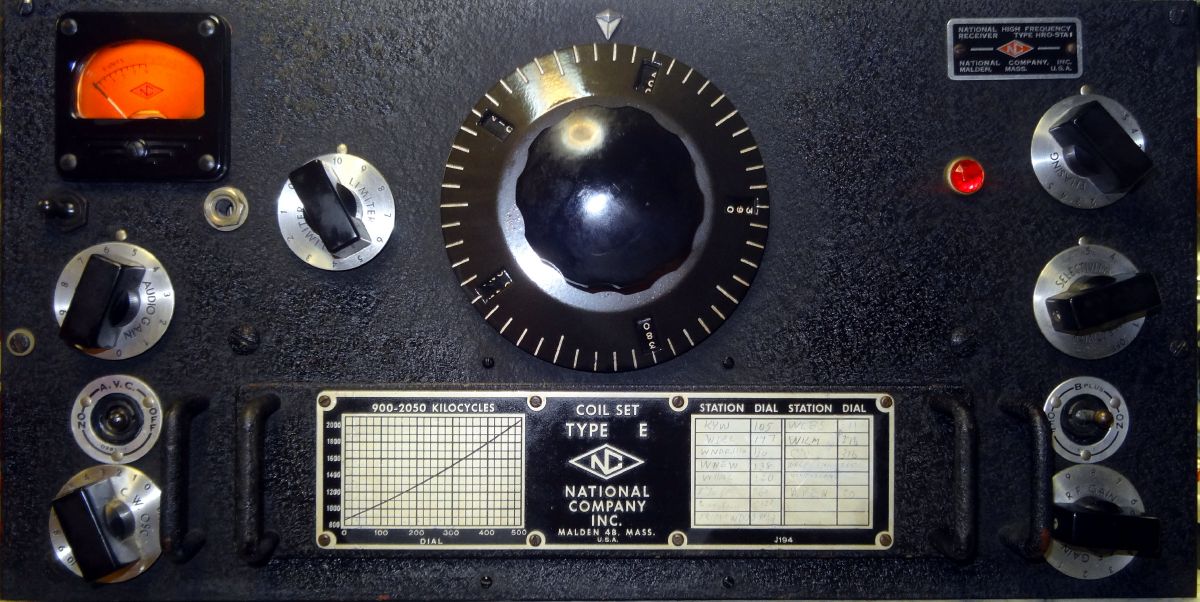
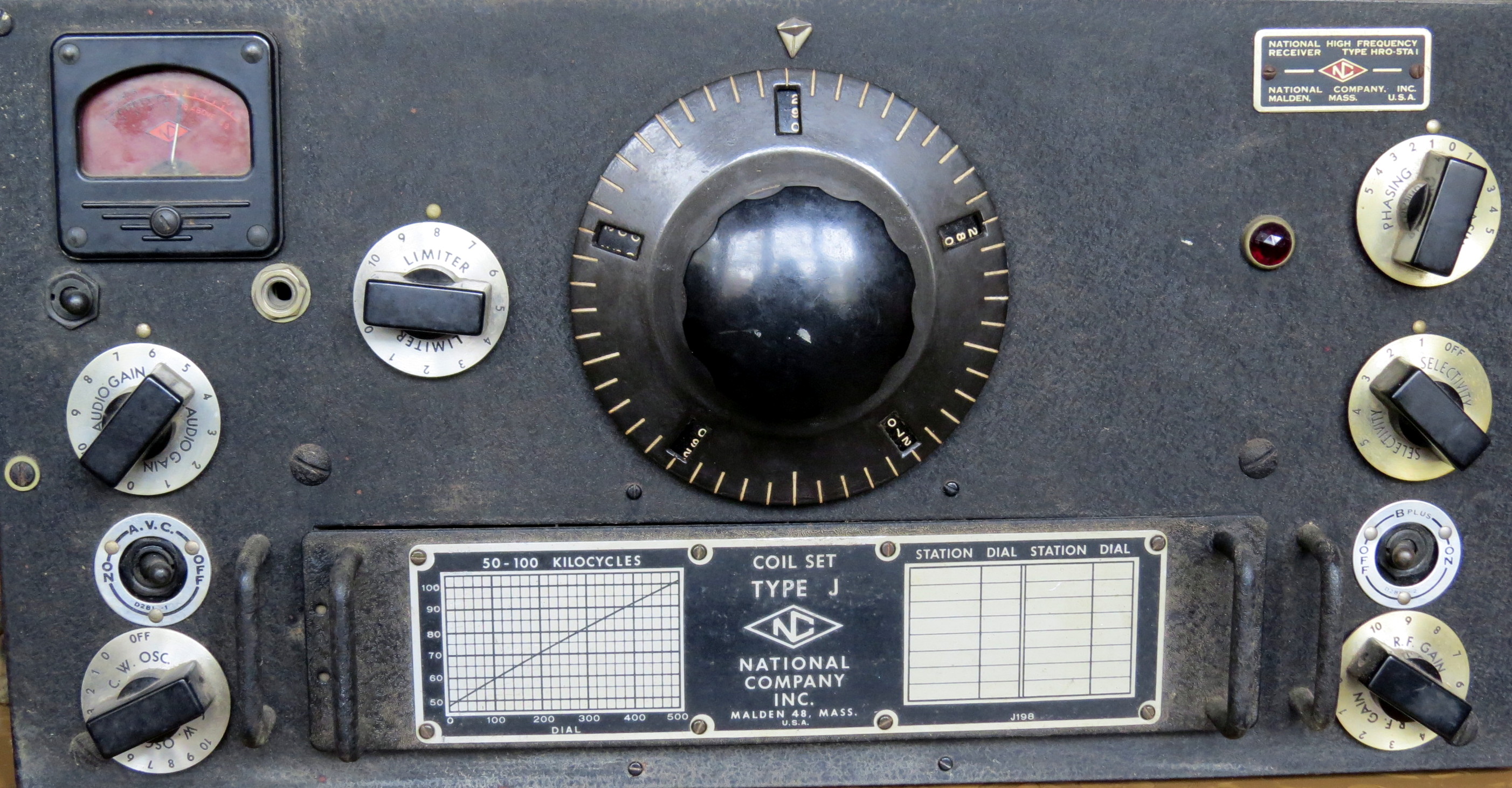 This was what the receiver looked like as received. As you can see it needed some cleaning and the S meter needed some work but more on that later. The lead front panel photo on this page is what it looked like after restoration.
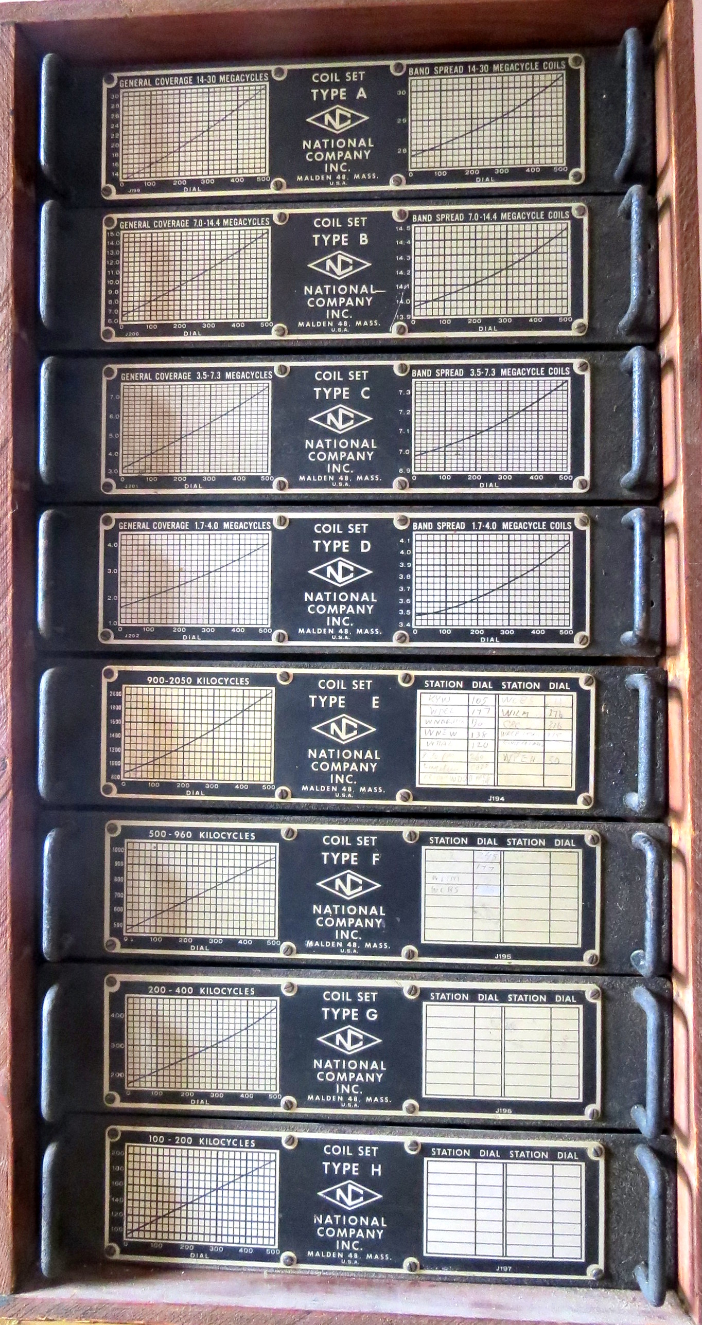 Photo of the coil sets in a large wooden holder. Eight shown here and one in the receiver.
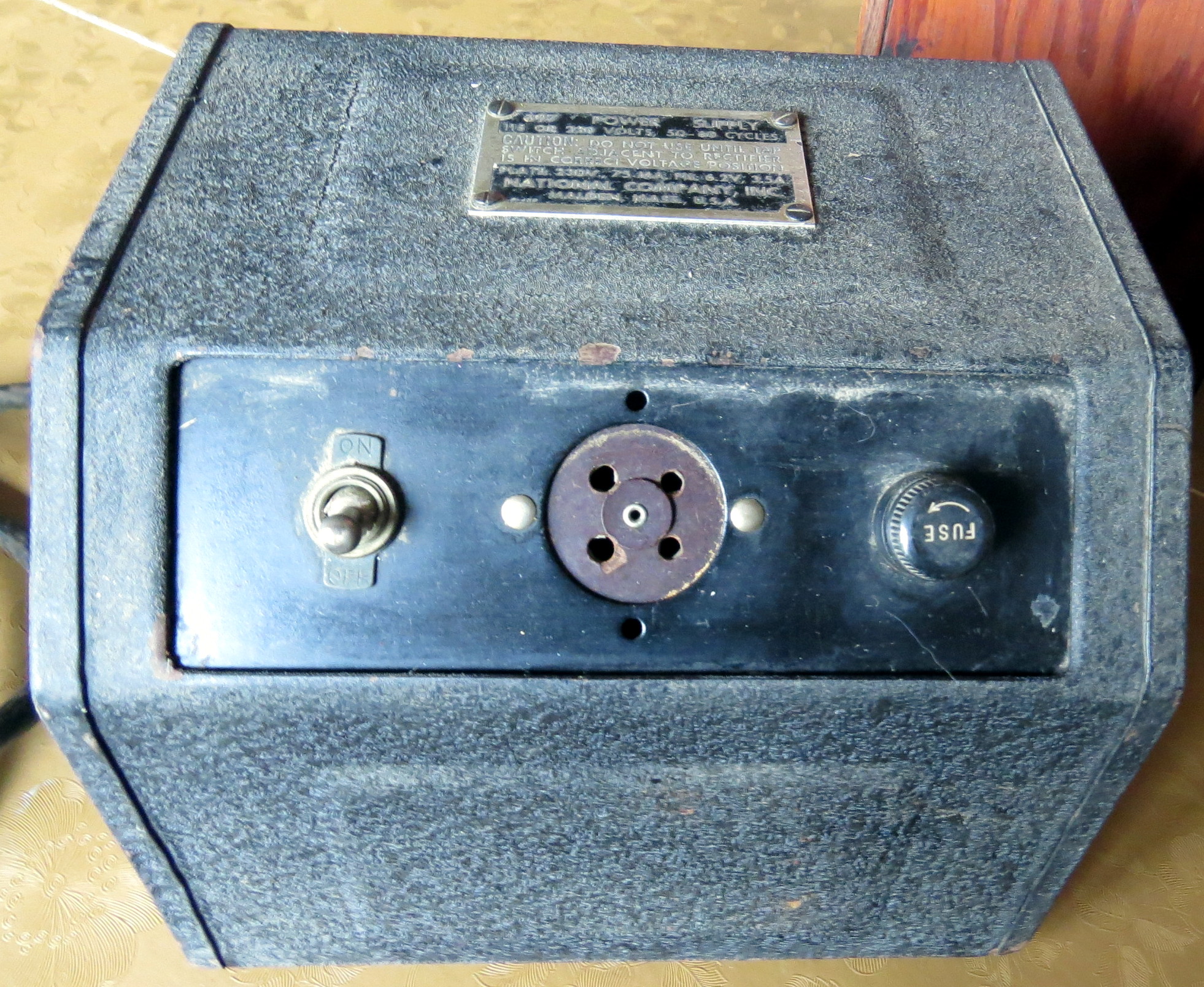 The receiver came with the standard "dog house" power supply but it turned out to be defective so more on that later.
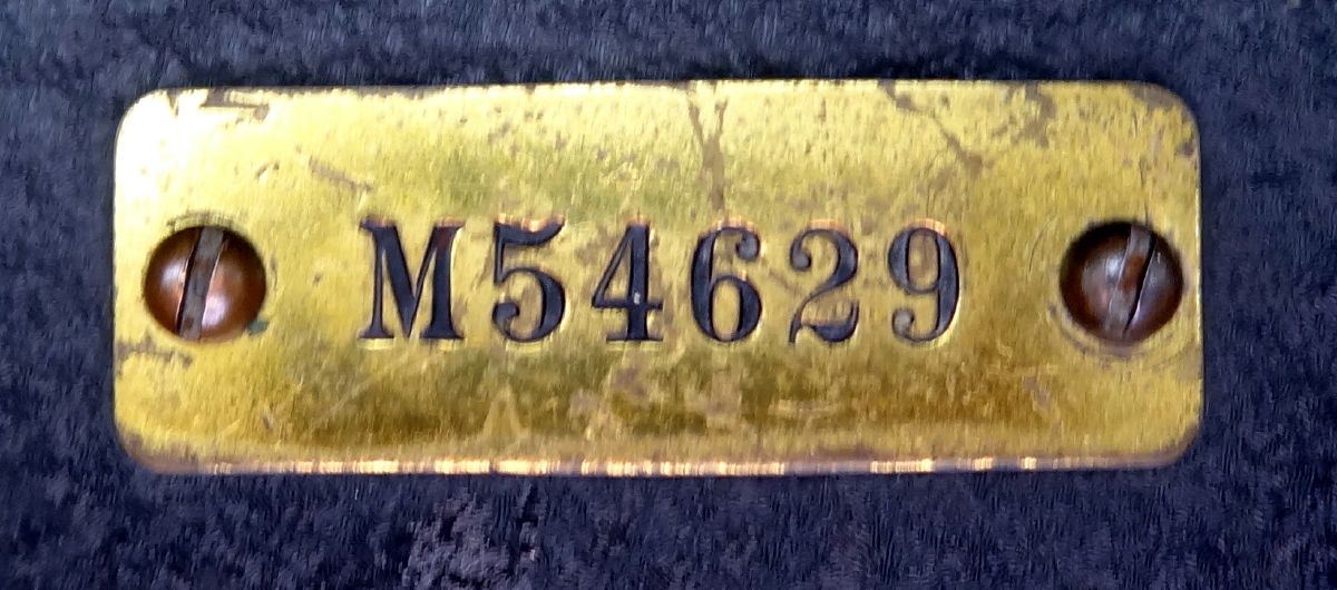 This is not a National serial number but rather an asset tag added to the receiver by an organization for tracking purposes.
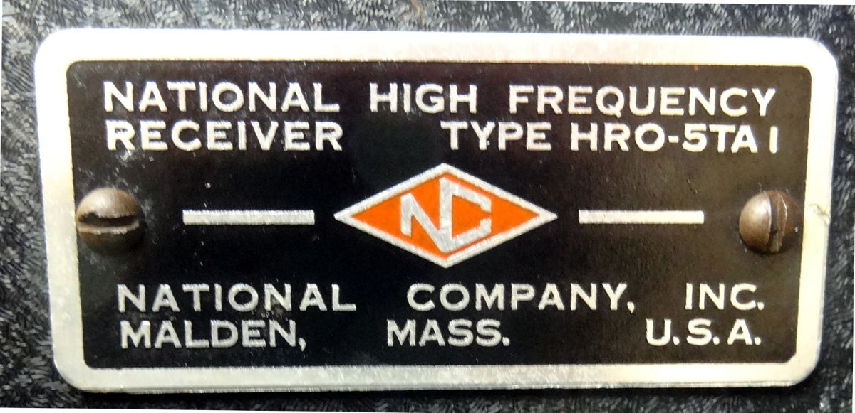
 The serial number was obscured by some chassis corrosion but some location help from Henry, WA7YBS and some WD40 and sanding made it visible.
The first order of business was cleaning the radio. I did this on a very hot sunny day. I covered the IF can holes with painters tape and poured a mixture of Simple Green Extreme Aircraft and Precision Cleaner and water over the entire chassis, scrubbing with a small brush where necessary. This cleaner works great even without a lot of scrubbing. Then a quick rinse with water and a dry out in the sun. The radio then set inside for several months until I was ready to begin the restoration.
I finally got to restoration of the receiver after Christmas 2018 and completed it in the second week of January 2019. A restoration of this age (70+ years) generally needs replacement of the capacitors that would commonly go bad. I had stock of most of the capacitors but I did place a replacement order and ordered a few specific caps I needed for the project. I generally order from Just Radios. They offer a large selection of capacitors and resistors as well as other items.
Under Chassis Restoration
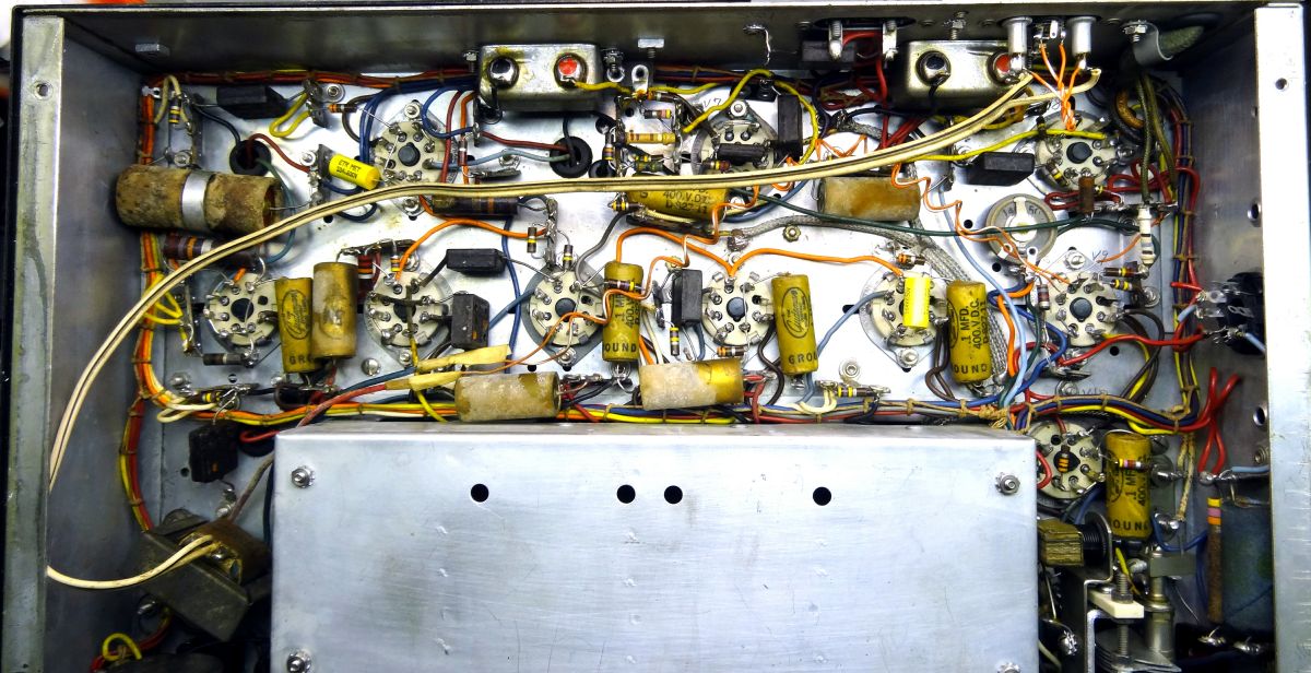 This is what the bottom chassis looked like after cleaning. You can see some of the minor mods that were made but not neatly done.
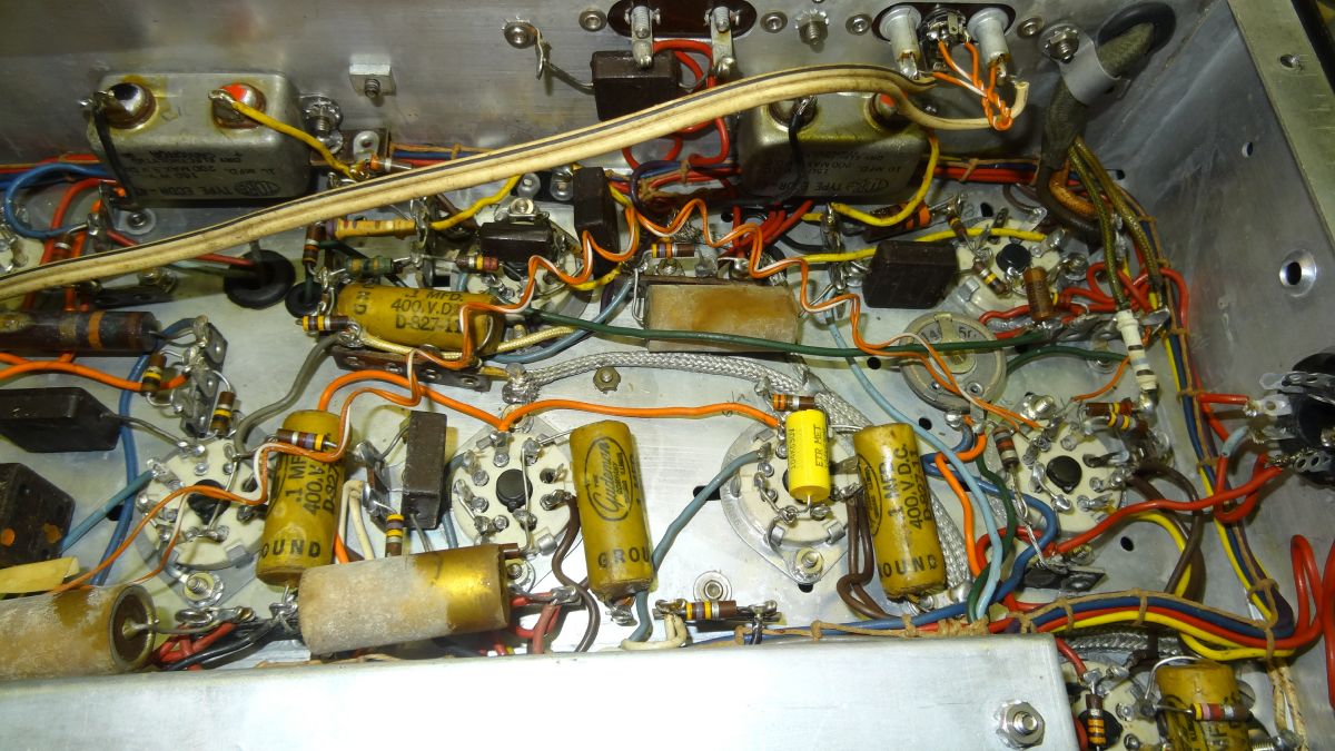 This photo shows the wiring to an output transformer that I retained but moved and cleaned up the wiring in my later restoration. Note one cap has been replaced (bright yellow). This shows the difference in size. All tubulars shown are .1 uf
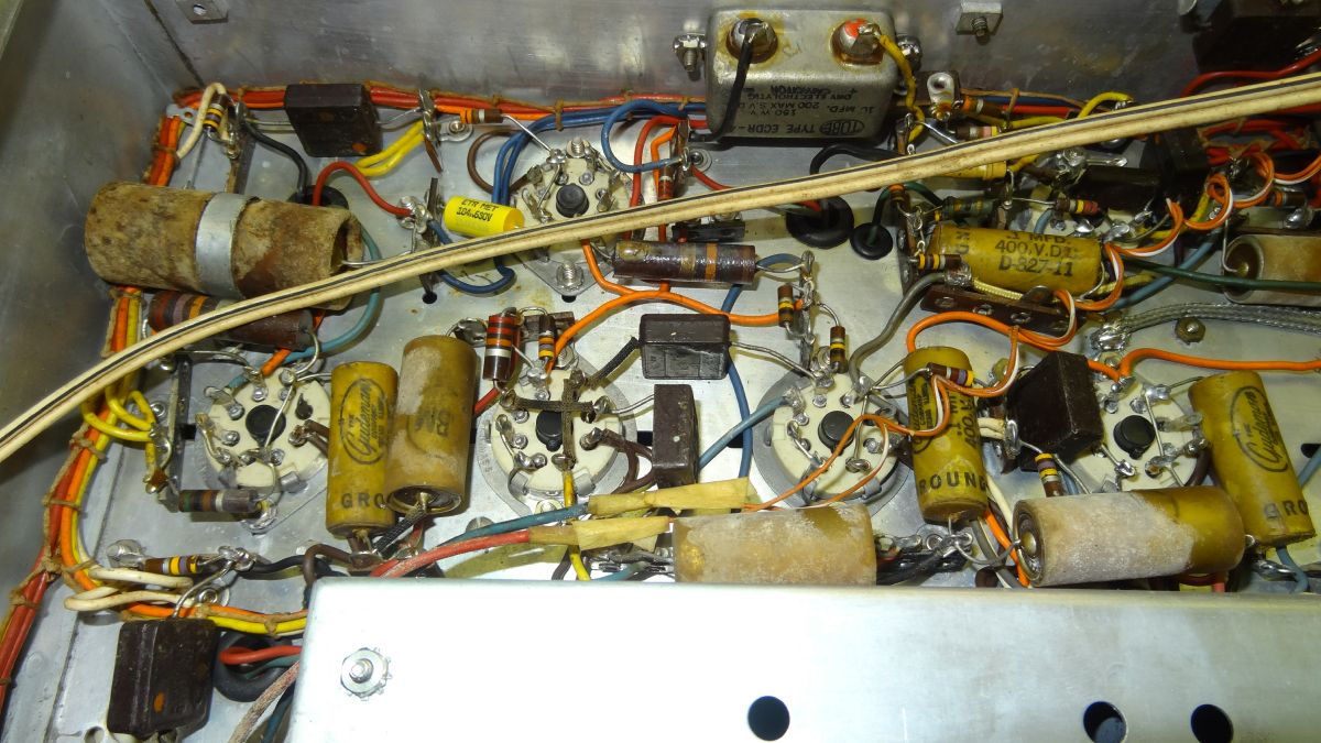 Another view of the left side under chassis. Again one cap has been replaced.
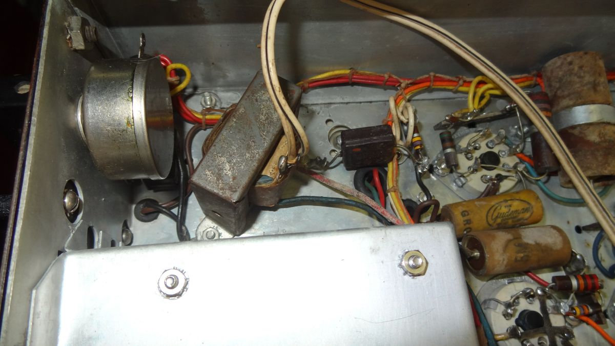 Just behind the front panel RF gain pot a prior mod place the audio output transformer. This has been relocated in the restoration.
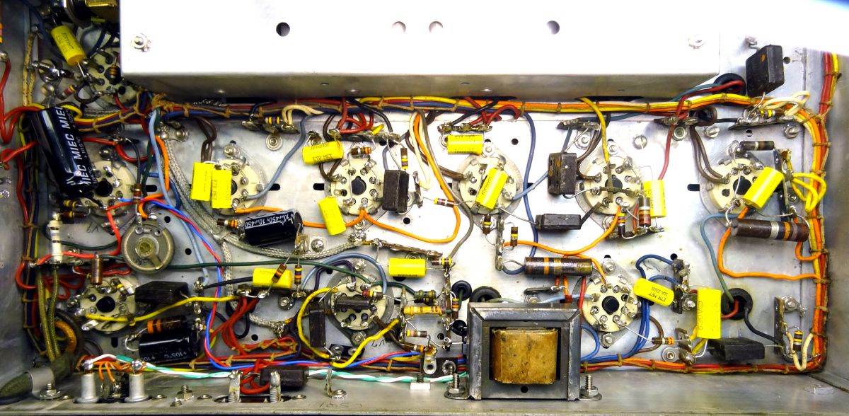 The completed under chassis restoration. Capacitors replaced, Audio output transformer relocated to back panel and rewired. The large black electrolytic at the upper left is an additional 100uf 450v on the B+ line.
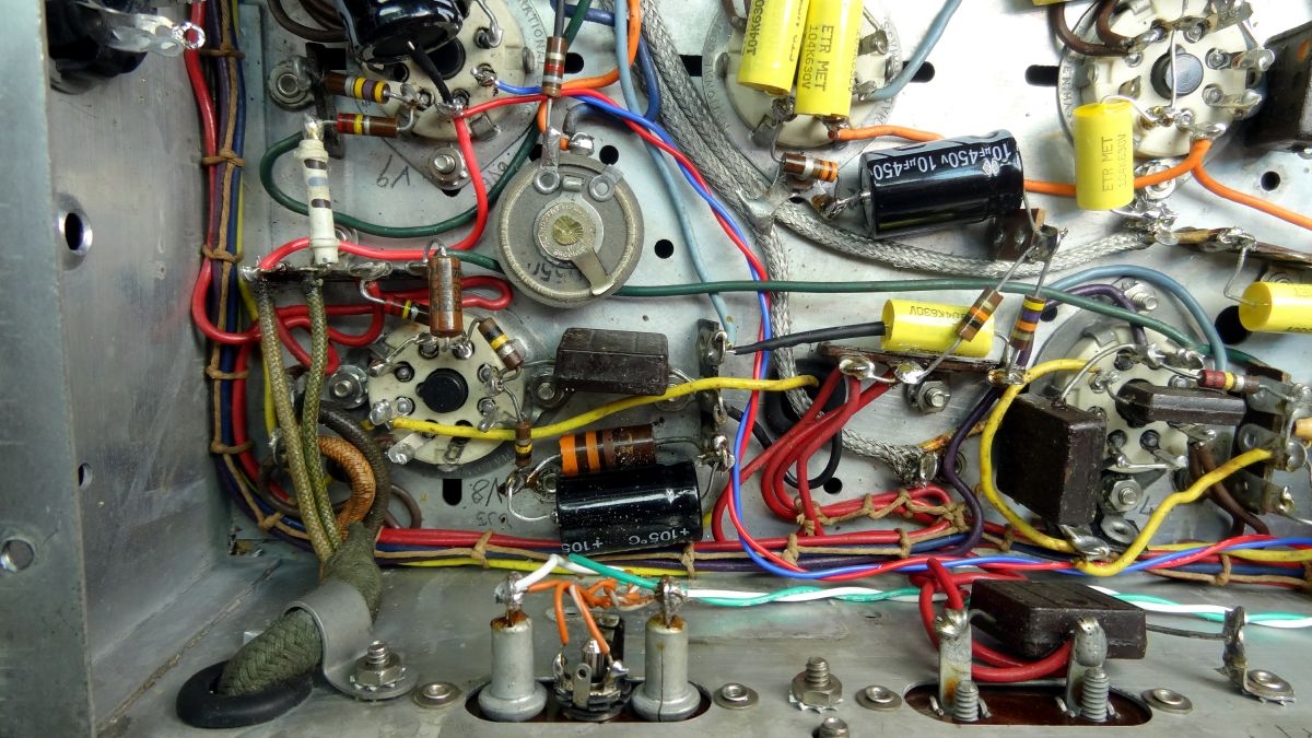 Closeup view showing former modification inserting a miniature phone jack in the center of the original speaker connections.
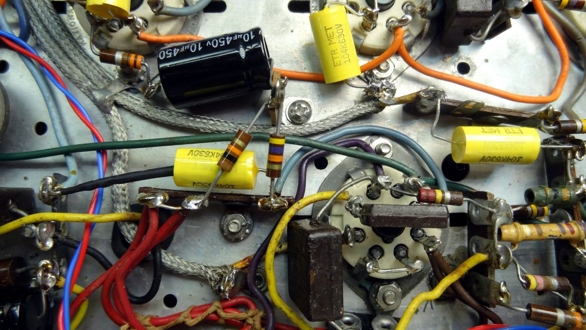 View showing the modification to reduce audio hum. A 10K resistor from B+ to a single terminal strip is inserted in series with the original 47K V7 plate resistor. A 10uf electrolytic goes to ground at the junction of the two resistors.
 Another closeup view of the left side chassis bottom
The above photos show the below the chassis HRO restoration. All tubular and bath tub capacitors have been replaced. About 1/3 of the capacitors were out of tolerance or leaky. I highly recommend replacing all of them regardless of their condition. I especially replace bath tubs or oil filled capacitors. I don't believe the oil used in the lower voltage ones is hazardous but if they leak, and many do, it makes a real mess. I see no reason to keep old parts that are prone to failure. The new caps are also considerably smaller than the originals allowing much shorter leads and lead inductance resulting in better bypassing.
The receiver had been previously modified to include an internal audio output transformer. The HRO's had the transformer in the speaker and the full B+ and audio output plate were plugged into the back. Also there is a terminal strip on the back that switches B+ to mute the receiver. It is amazing how dangerous products were in the past allowing high voltage to be exposed. Methods that would never be used today. Having the internal audio output transformer and mini phone jack make it easy to safely connect any low impedance speaker directly to the receiver. The transformer was relocated to a convenient place on the rear panel in a location formerly occupied by one of the bath tub capacitors. I also put electrical tape over the rear (muting) terminal strip preventing any accidental contact. This is in parallel with the front panel B+ power switch so it is not necessary to jumper it.
The receiver performed well but like many receivers there was a low hum from the speaker with the volume turned all the way down. Most would except it as normal but it bothered me and I figured I could fix it. I discovered that upon inserting a phone plug into the front panel headphone jack the hum completely went away. This isolated the problem to the 6SQ7 (V7) audio driver plate which is feed directly from the B+ line. Unlike modern designs where electrolytics are used to decouple and filter lower level stages you do not see this in the HRO. There is no low frequency B+ filtering within the receiver itself. Perhaps it was because of the cost and size of electrolytic capacitors at the time. The answer, which can be seen in one of the above photos, was to insert a 10K resistor in series with the existing 47K from B+ to the plate of V7 using a vertical one terminal strip. At the junction of the 10K and 47K resistors a 10uf 450V electrolytic was placed to ground. This completely eliminated the low level hum from the speaker. This modification might be useful in most any version of the HRO since the "dog house" power supply had minimal filtering with just 8uf electrolytics on either side of a choke. Since the "dog house" supply that came with the receiver failed I was unable to test it with the original supply.
Power Supply Construction
I tried my best to save the original supply but there apparently was shorted turns somewhere in the primary windings. The transformer and choke were potted in tar and I had no intention of melting it out. Besides the fire hazard and breathing hazard it would be a mess and really not worth it. The idea here is to preserve a fine old receiver. Power supplies are a dime a dozen. Fortunately my home parts store is well stocked and I gathered together the required parts to build one. I removed the tube sockets and 80 rectifier from the old supply. Sometimes you have to make decisions about what is good and what is bad or not worth repairing and in this case the old "dog House" went in the trash. Below are some photos of the new supply. It is a choke input and supplies about 210 volts of B+. Apparently the original supply was spec'd to put out 240V but the manual also shows a DC version that had a B+ of 165V, a very wide range. I usually like to go on the low side and since my line voltage is typically very high (over 125V) I suspect the original supply without some bucking would have been too high. I like to see filament voltage of around 6V and in this case the plate voltage of around 200-210V was plenty adequate.
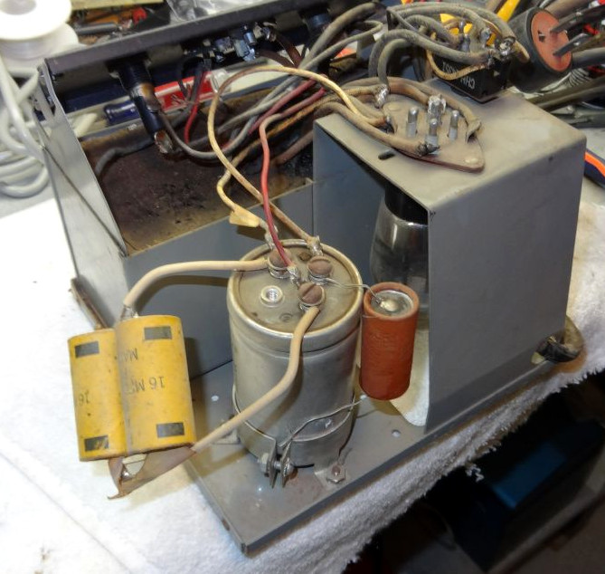 Bad supply. Someone had paralleled electrolytics.
 Another view. Notice cutoff grounded plug. I doubt that was original.
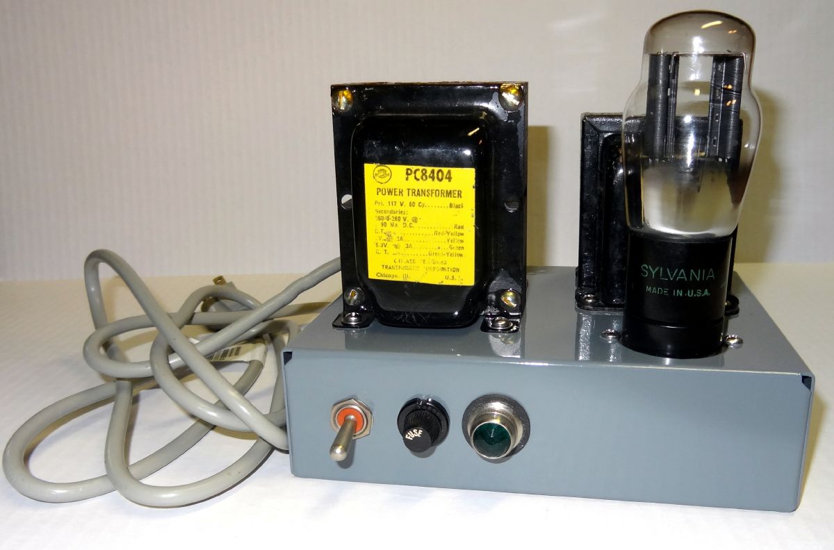 Front view of the new Power Supply. Stancor PC-8404 transformer, 80 rectifier, and 12h 200 ohm choke. Below the chassis is a 100uf 450V electrolytic and a 200K bleeder. It is a standard full wave choke input supply
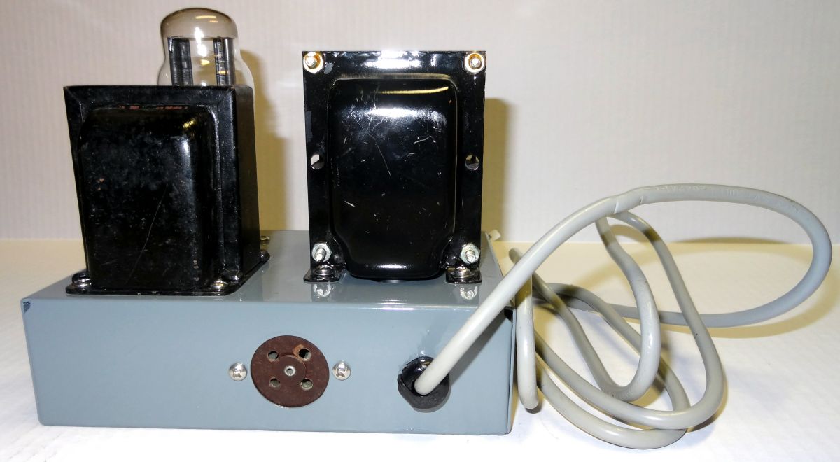 Back view of the new power supply. Of course a grounded plug and the 4 pin mating connector to the HRO power plug.
Above Chassis Restoration
 As you can see in this photo there are a couple of places where our rodent friends have caused the chassis plating to rust through. I was going to grind this down and paint over but it obviously has nothing to do with the operation of the receiver.
Mechanically the tuning was smooth and the controls even without cleaning were noise free. Quite an achievement for a receiver that is 70+ years old and has been setting in not the best environment for some of that time. A few things topside did need attention. The S meter glass had been pushed in and in turn pushed the meter needle against the front plate making it inoperable. This required removal of the meter from the chassis. Once removed three screws around the rear perimeter were remove allowing the meter to be removed from its housing. There is a retention ring that hold the glass against the front of the meter face. This ring had been pushed back. I carefully tapped it back using a small screw driver against the edge and moving around the perimeter. Be very careful if you have to do this as you do not want to break the glass. After the glass was tight against the front I cleaned everything very well. I then carefully pulled the needle back to position. Before reassembly align the adjustment tab on the meter to its center position and the adjusting screw tab in the housing to bottom center. Carefully reinsert the meter into the housing making sure that the meter needle has free movement once it is installed. Reinstall the screws and meter into the front panel. The original Pilot light was broken so I installed a new assembly. This probably had a 6V lamp in it but I always install 12V replacements for two reason, one I have lots of 12V lamps, and two they provide plenty of light and will have a substantially longer life.
 S meter disassembled
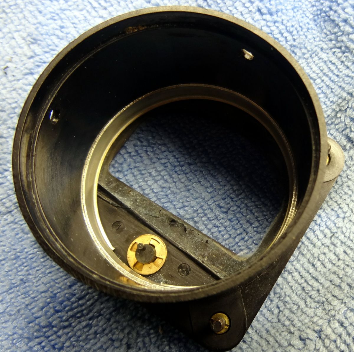 S meter housing showing retention ring
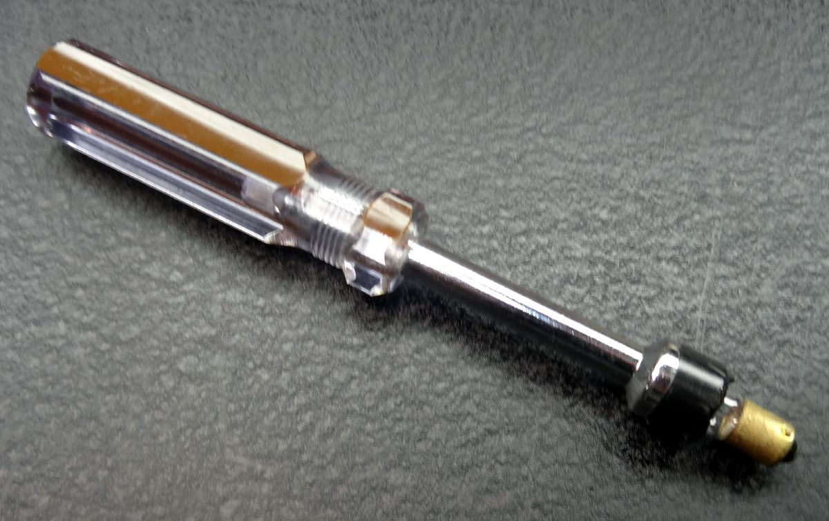 Tool to remove pilot light.
As received the receiver had a glass 6L6 in place of the 6V6 audio output tube. While this worked fine in does draw more filament current and is really unnecessary so I replaced it with a metal 6V6 from my stock. This produced no real difference in audio output or quality. The front panel red pilot light was out. So how to replace it. It is impossible to get to it with your fingers so I fashioned a nut driver with some black electrical tap to snugly grab the bulb. It is a bayonet base so pushing down and turning allowed removal.
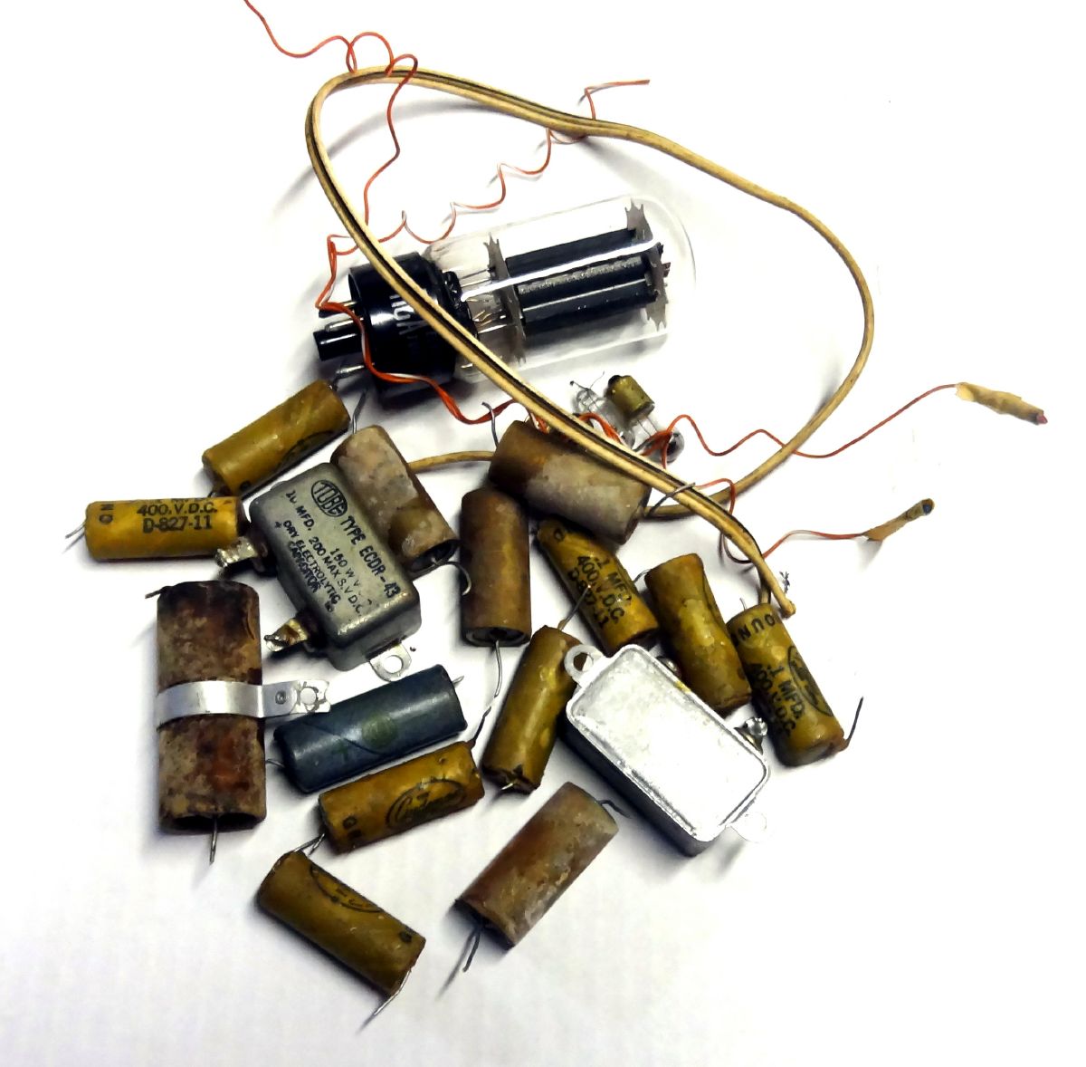 Photo of parts replaced in the restoration.
The final result was very rewarding as the receiver worked flawlessly. Of all the restorations I have done this was by far the easiest I have done. Electrically the compo nets are easy to get to with plenty of under chassis room. While not as fancy as today's receivers it was certainly a fine receiver for its time. National Radio and the HRO series of receivers have a definite place in the radio history of the United States. I am sure the gentleman that owned it would be happy to see it restored to its old glory.
National Radio Links
- Wikipedia National Radio
- A brief history of the National Radio Company
- Western Historic Radio Museum (very good history site)
- 1947 National Radio product catalog
This page last updated 1/12/2019
© 2019 - WA3DSP