Multi-Elmac A54 Transmitter Restoration
A54 Description
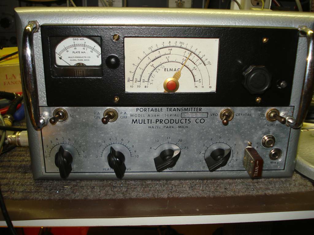
The Multi-Elmac A54 and A54H are (AM) plate modulated mobile transmitters manufactured in the early 1950's. They were VFO or crystal controlled and covered five bands, four fixed and one assignable. The fixed bands were 75, 20, 11, and 10 meters. Yes, we had the 11 meter assignment in the early 50's. The assignable or "X" position on the band switch could be field modified to any one of 160, 40, 15, or 6 meters. The final tube is an 807 with push-pull 6L6 modulators. The A54 ran on nominally 500V @ about 200 milliamps and a filament voltage of 6.3 or 12.6 volts. It was a simple but rugged design and in good shape and properly aligned these transmitters give excellent results. The A54H has a 6AU6 microphone pre-amp for use with a high impedance crystal or dynamic microphone while the A54 is designed to be used with a carbon microphone.
My restoration
I acquired my A54H on Ebay. It was not in great shape but was certainly restorable. The first thing I did was completely remove the front panel. A former owner had insalled a modern four pin microphone connector but other than that there were no additional holes or modifications. The nice thing about the Multi-Elmac transmitters is the removeable aluminum bezel with all of the lettering. Removing the bezel, meter, and handles allows you to clean and, if necessary, repaint the panel. Most of my restorations start with a thorough washing. I usually spray everything down with an ammonia, soap, and water mixture, using a toothbrush to scrub hard to reach places and then spray rinse with hot water. Then it goes on top of the heater in the winter or in the sun in the summer to dry. Since this is the first thing I do, it is quite awhile, often months, before any power is applied. I know this is not the preferred way to clean electronics but in really dirty cases, and most of mine are, it is often the only way. I have never had an issue cleaning this way but you do have to be careful with paper components and markings that can be removed with the washing. I painted the front panel and case with gray hamertone paint and reassembled the front panel. Years of grime were buffed off of the the front panel switches and the handles. At this point it was ready for electrical restoration.
The components and wiring were all original. The original wiring was rubber insulated with a cloth outter cover. It was intact but in some cases the rubber was dry and would crack if bent. I replaced many of those wires, especially if they carried high volage. When restoring I have a number of objectives. Number one is safety. I would never use a double fuse plug and I always replace a two wire power cord with a grounded wire and plug unless it is a transformerless design. I also have no problem with sane modifications that improve the performance as long as they do not physically alter the front panel. I have taken this approach with the A54 and have made a number of circuit changes that I will detail here. I realize and respect those who would maintain absolute stock design unfortunately I would personally have a very hard time adhering to that.
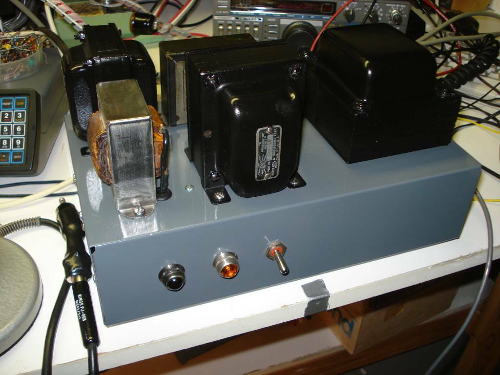 My Homebrew power supply used with both the AF67 or A54. It supplies 6.3VAC, 300VDC, 600VDC, and 12VDC for PTT. See the schematic in the links section below.
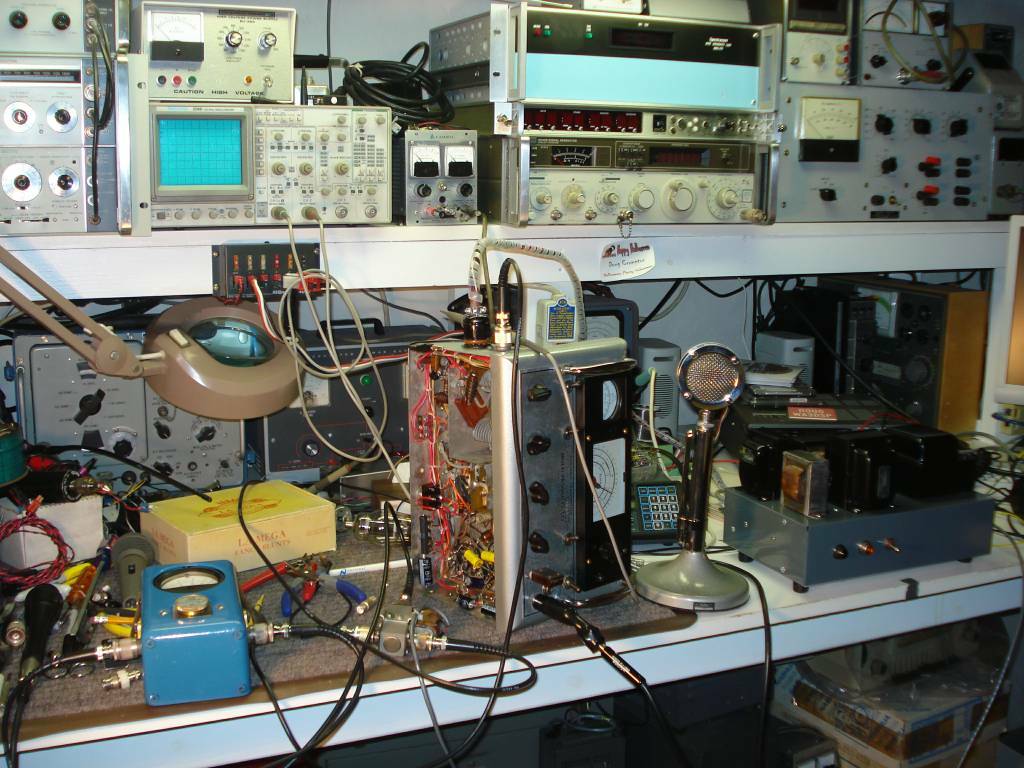 One of the test benches at WA3DSP, A54 on side, Power supply and D104 to right, and antenna relay and Bird wattmeter at left.
The first change was removing all of the 10 watt series dropping resistors and establishing both High voltage (500-600VDC) and low voltage (300VDC) supplies within the A54. This improves efficiency and also reduces the heat generated under the chassis. It is also a much cleaner way to do things. The AF67 uses dual voltages and I already had a Power supply built so it was quite easy to adapt it to the A54. There is a spare pin on the 8 pin Octal power connector that can be used for the low voltage. I also always wire these mobile rigs for 6 volt filaments only. This eliminates any potential series filament imbalances. My theory is that in the odd chance you would actually ever want to run this rig mobile on 12V car power you could use a very efficient 12VDC- 120VAC inverter to run the entire power supply. A 200-300 watt inverter should be more than adequate.
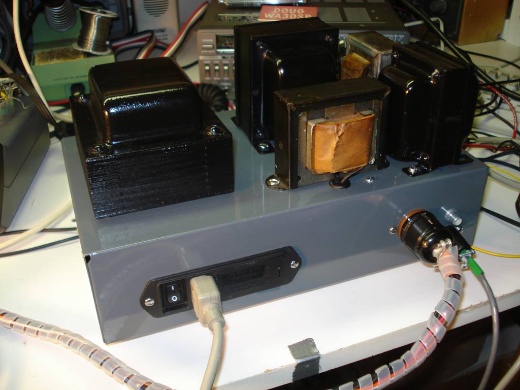
Power supply rear view. It uses a Corcom AC filter and fuse module, Power out is through 11 pin octal socket, 2 pin Jones connector for Antenna relay control, and RCA plug for receiver muting
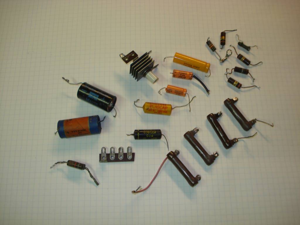
Some of the parts removed or replaced during restoration. Selenium Rectifier was used in the negative peak modulation limiting circuit and was replaced with a silicon diode.
The stock A54 has a rather weird power switching arrangement. There is a PA on/off switch on the front panel which, in the off position, disconnects the +500VDC from the final and shorts the modulation transformer secondary. I am not sure what the Elmac engineers envisioned here but it seemed like something looking for a modification. My dual voltage change complicated this a bit but I was able to rewire the circuit so that this switch turns off power to the final, audio stages, and modulator in the in the off position but the +300VDC remains on for the rest of the RF circuitry thus allowing you to key the PTT to spot the crystal or VFO frequency. I also added a rear panel DPDT toggle that switches between CW and AM. In the CW postion the +300 and +600 are removed from the audio and modulator stages and the secondary of the modulation transformer is shorted. This is the way it should be done. Elmac adopted a similiar method in the later AF67 transmitter.
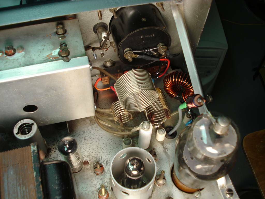
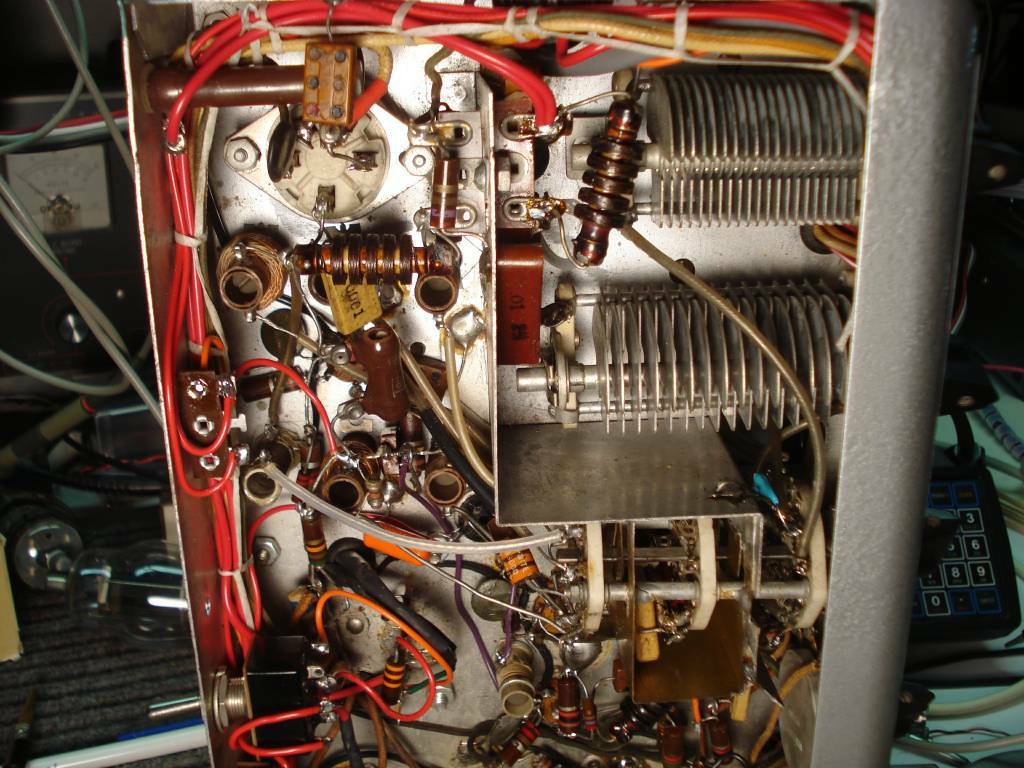
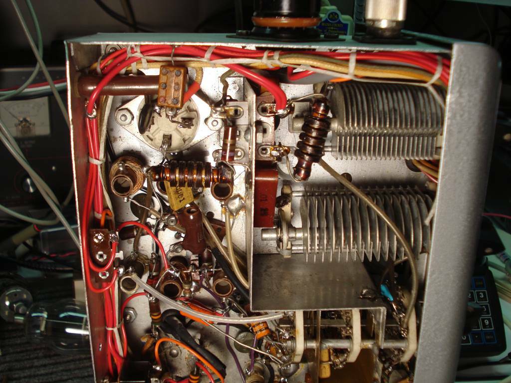
View shows PA power switch partially obscured behind the 40 meter tank coil. Note diode protection added across meter terminals. The toroid tank coil is for 80/75 meters.
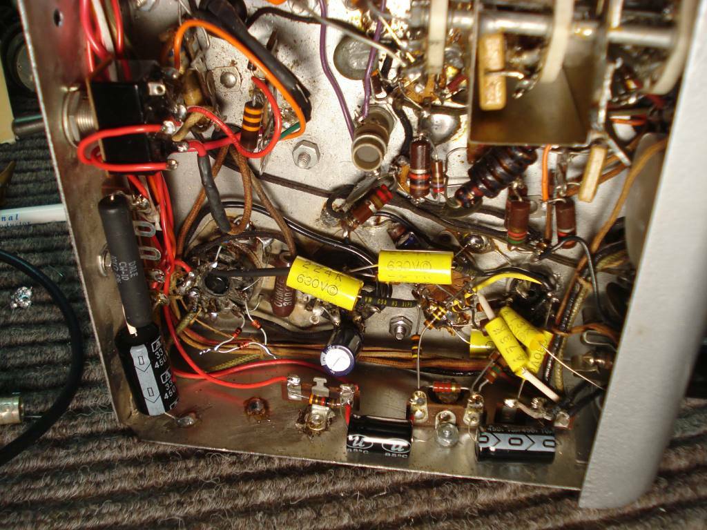
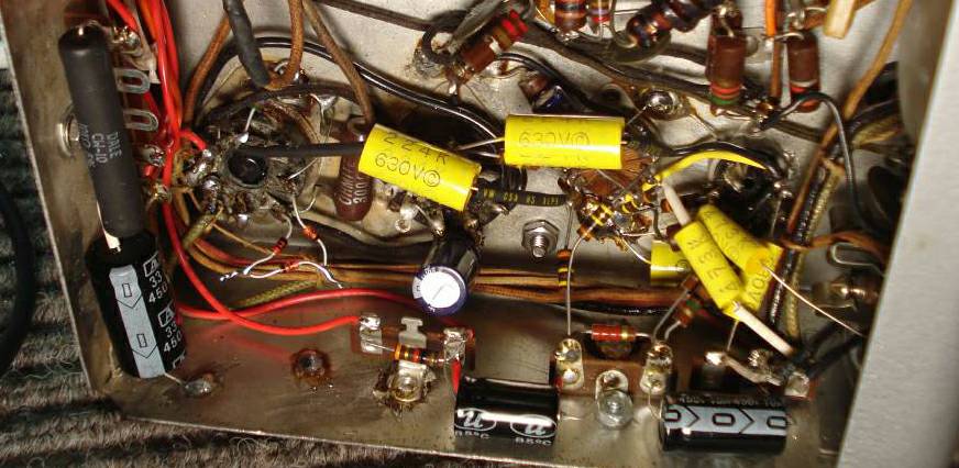
Bottom view showing the AM/CW DPDT toggle switch added to the rear panel. The 10 watt resistor to the left is the voltage dropping between the +300 and the VR tube. The entire audio section was rewired with a few minor changes. All Capacitors and many resistors were replaced in the audio section. The series zener diodes at the 6L6 modulator socket total +22VDC bias in the cathode circuit.
The audio section was mostly rewired. A good solder sucker is your friend! The push-pull 6L6's in the stock A54 are cathode biased with a 300Ω 5 watt resistor. I paralleled zener diodes totaling 22VDC. This established the correct bias for class AB1 operation. The newer AF67 uses a negative grid bias (22 volt battery or equivalent) to establish this. Using cathode bias creates the same effect albeit at some loss of efficiency. The push-pull 6L6's run quite well with 600VDC on the plates and 300 volts on the screens. In my AF67 mod I regulated the screen voltage at 275VDC with a FET regulator but I did not see a need to do that here. Most of the other audio circuitry remains unchanged except for an increase in the first audio grid leak resistor. I use these rigs with a D104 microphone and for best response characteristics it likes to see a very high input impedance preferably 5MΩ or more. The stock A54 had a 1MΩ pot at the microphone input to the 6AU6 grid. The pot was moved to between the output of the 6AU6 and the 12AU7 grid and the 6AU6 grid leak was made 10MΩ. Both coupling capacitors and cathode bypass capacitors were increased in size to improve the frequency response. Note liberal supply bypassing; the new caps are larger in value and much smaller in size than the originals. This makes the under chassis much less crowded. Also a key feature of the Multi-Elmac chassis is the ability to solder to it wherever you desire. Simply scrap it clean and use a large iron, I use a 250 watt gun. You can solder on terminal strips rather than drilling a hold and screwing them on. See the schematic changes for details.
Closeup view of the audio section. 6L6 modulators to left, 12AU7 center, and 6AU6 at right. I always make the mistake of being too much in a hurry and not taking "before" pictures. Suffice to say things look a little different and cleaner in this "after" picture.
Mid-section view showing back panel AM/CW switch at lower left
View showing 8 pin octal power connector. Wiring harness is re-laced with nylon cord.
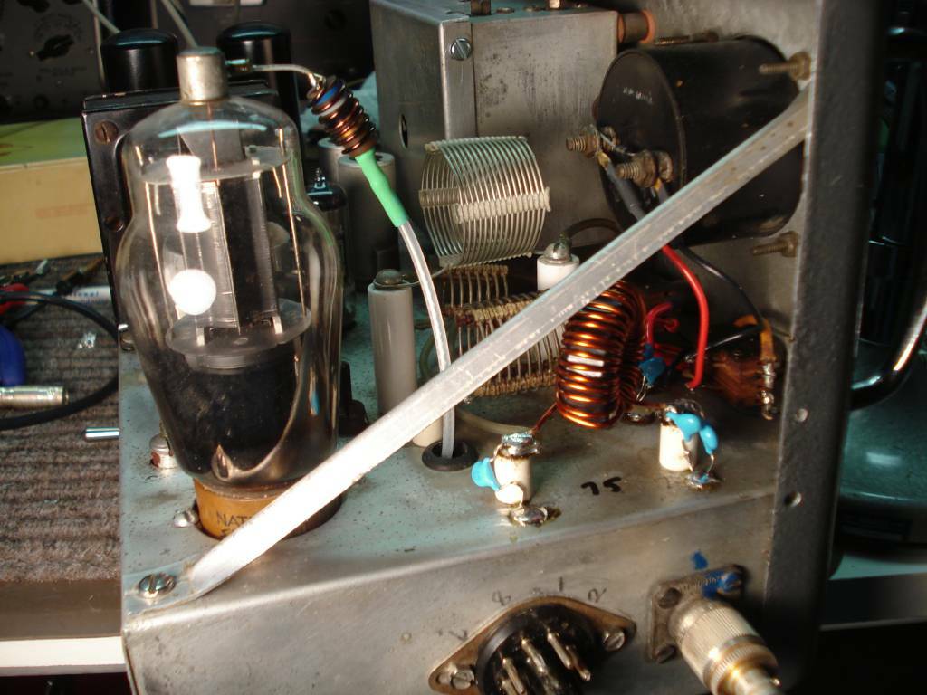
80 meter toriod wound plate tank. Larger coil sticking up between 807 and meter is larger wire size 40 meter tank replacement.
The Elmac mobile transmitters used B&W style coil stock for the plate coils. To minimize size these coils, especially for the 160-40 meters bands, used very small wire. They were fragile to begin with and the plastic spacing material is often deteriorated after 60 years. In my AF67 mod I used a toroid wound tapped coil for 160 through 20 meters. The A54 uses individual coils for each band and unless you rewire the tank circuit you can't use the tapped approach. The 80 meter coil in my A54 was smashed beyond repair. I had a replacement coil but I did not like the small wire size so instead I wound the 80 meter coil on a toroid with much larger wire. The A54 has rather small plate and loading tuning capacitors. The plate is 100pf and the loading is 200pf. I wanted to up the 'Q' somewhat as the orginal design seemded to be in the 8-10 range. This required additional capacity placed across both the plate and loading capacitors. Fortunaltely this is very easy to do in the A54 as the band coils are entirely swithced in and out. You can place the additional fixed capacitors on either end of the tank coils as needed.
The A54 schematic showed the plate blocking capacitor and plate choke AFTER the plate tank coils allowing plate DC voltage on the coils and PA tuning capacitor. I am not sure if any were actually made that way but the one I restored had the blocking capacitor and choke right off of the plate where it traditionally and preferably is placed.
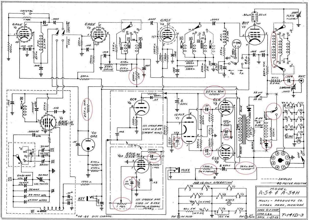
Original A54/A54H schematic with some of the parts that were removed, replaced, or changed circled in red. Kicad schematic coming soon for actual circuit changes.
- A54 Notes and manual (notes from past modification)
If you have any questions please contact me directly at Doug@Crompton.com