Heathkit SB220 Restoration
Heath Radio History (from Wikipedia)
Heathkit is the brand name of kits and other electronic products produced and marketed by the Heath Company. The products over the decades have included electronic test equipment, high fidelity home audio equipment, television receivers, amateur radio equipment, robots, electronic ignition conversion modules for early model cars with point style ignitions, and the influential Heath H-8, H-89, and H-11 hobbyist computers, which were sold in kit form for assembly by the purchaser. Heathkit manufactured electronic kits from 1947 until 1992. After closing that business, the Heath Company continued with its products for education, and motion-sensor lighting controls. The lighting control business was sold around 2000. The company announced in 2011 that they were reentering the kit business after a 20-year hiatus but then filed for bankruptcy in 2012, and under new ownership began restructuring in 2013. As of 2019, the company has a live website with newly designed products, services, vintage kits, and replacement parts for sale.
See https://en.wikipedia.org/wiki/Heathkit for more information on Heath.
Click on any photo for a larger view.
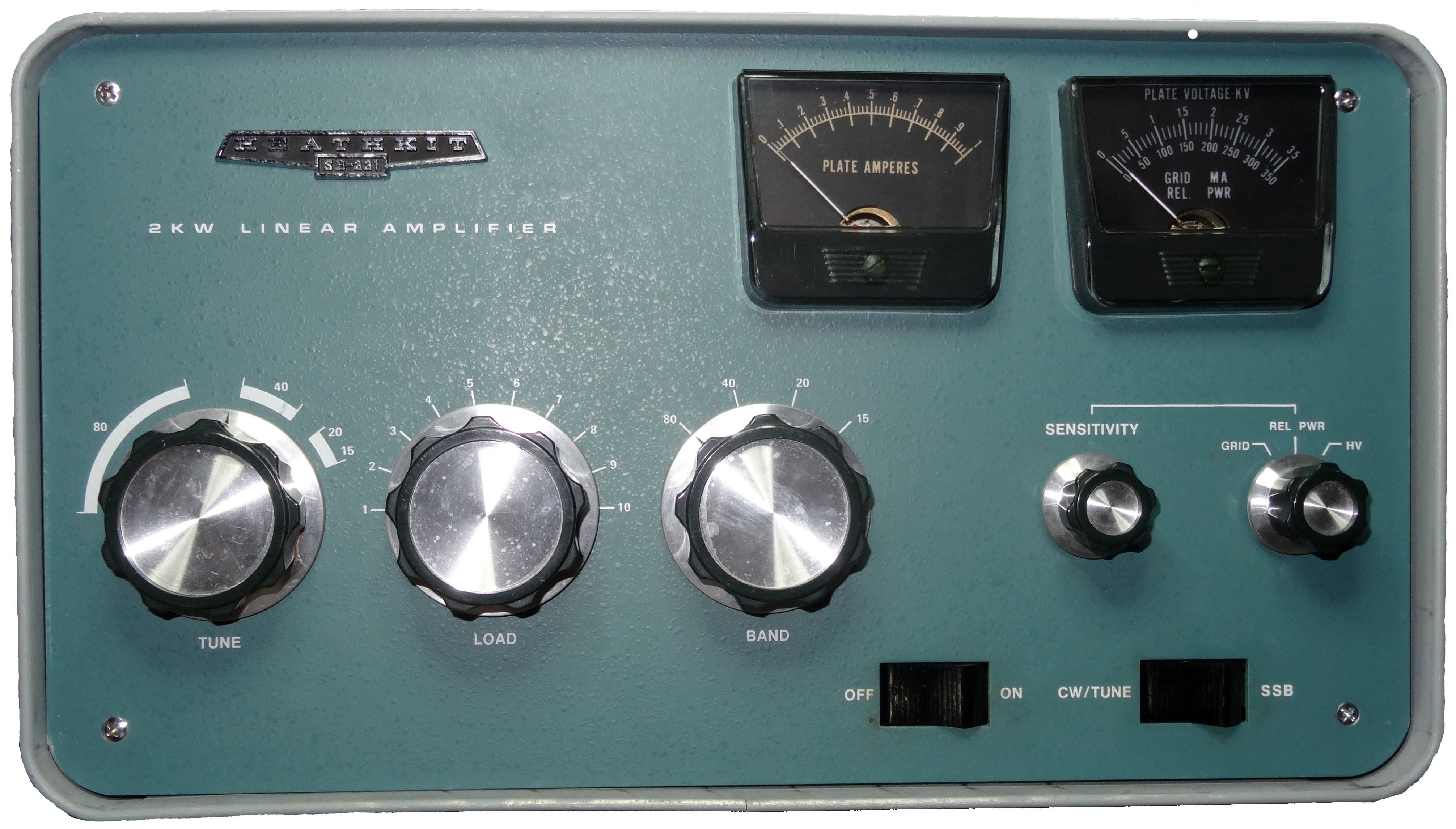
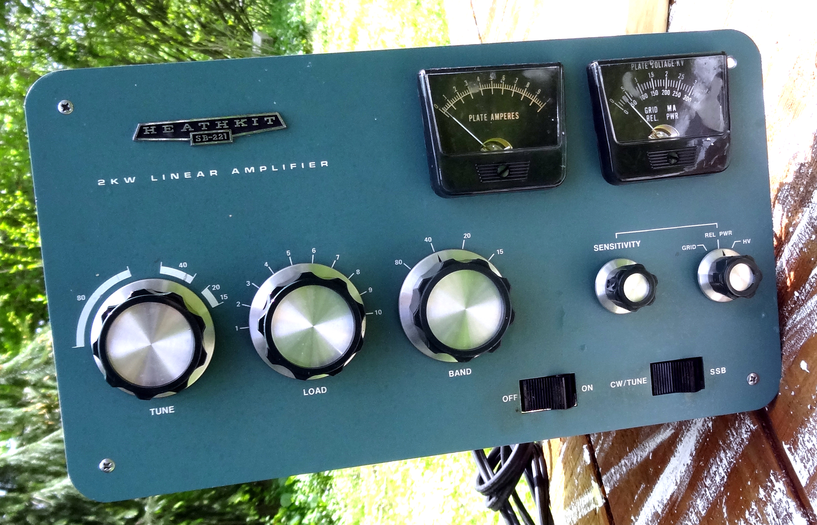
Welcome to my restoration and modification of the Heath SB220 amplifier. I previously restored and modified a Heath SB200 several years ago (SB200 Restoration) and I have been using it ever since. Unfortunately the 572B's which I bought new at the time have gone flat not because of abuse but because they are made in china and no where near the quality that these tubes were when the SB200 was introduced. I will still keep the SB200 and hopefully better and more available tubes will be made in the future. I hope you enjoy this SB220 restoration and if you have any questions you can email me at my QRZ address - 73 Doug, WA3DSP.
 The amplifier needed a bath and it was a nice warm sunny day. I used
Simple Green Extreme Aircraft and Precision Cleaner and then hosed it down. You can used dry compressed air,
moderate pressure, to dry.
The amplifier needed a bath and it was a nice warm sunny day. I used
Simple Green Extreme Aircraft and Precision Cleaner and then hosed it down. You can used dry compressed air,
moderate pressure, to dry. 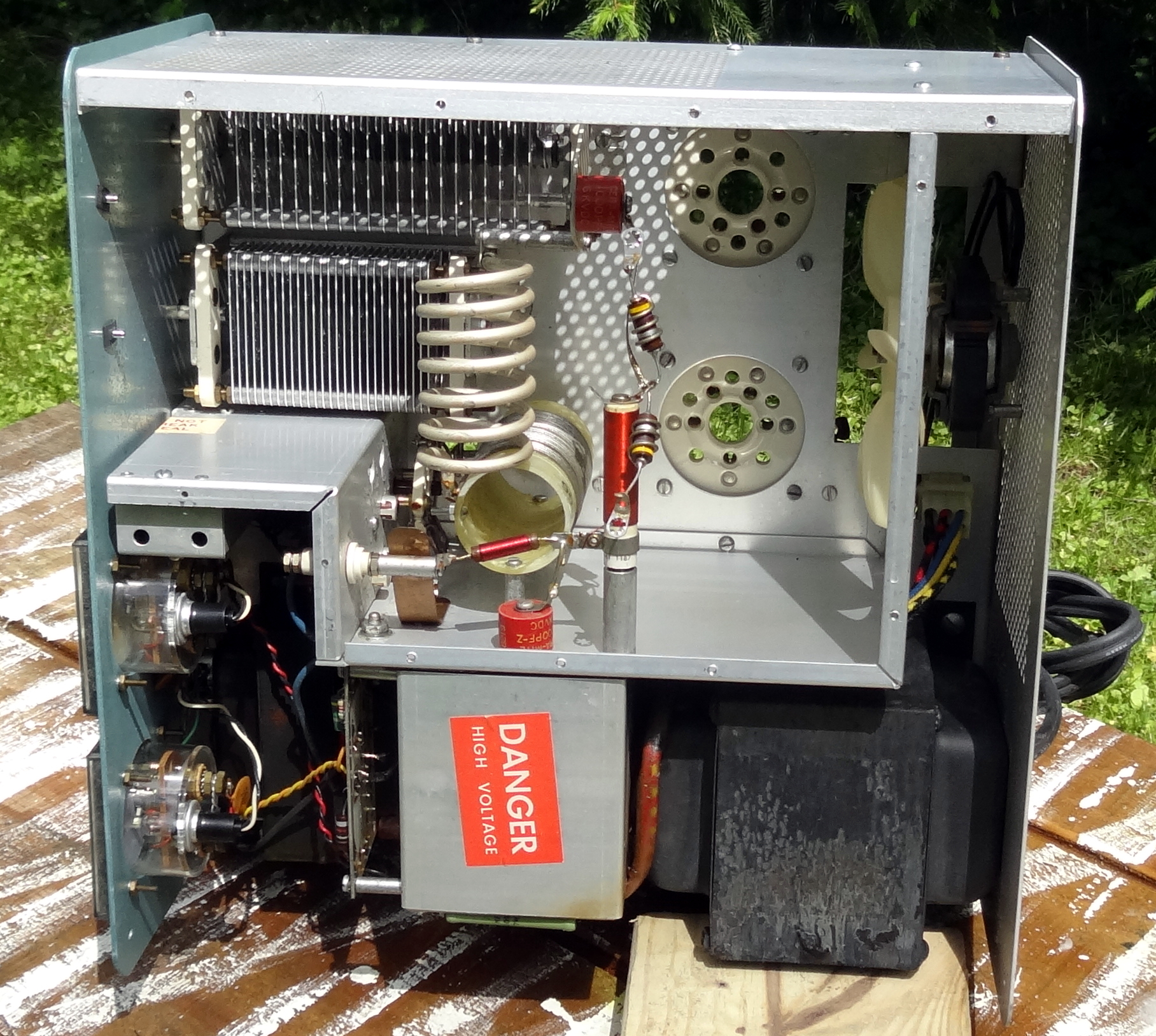 Be careful to not get water in the transformer and meters. Let it throughly dry. The sun helped
here and if you do get moisture in the meters (fogging) remove the push-in lamp to let it dry.
Be careful to not get water in the transformer and meters. Let it throughly dry. The sun helped
here and if you do get moisture in the meters (fogging) remove the push-in lamp to let it dry.
I received the amplifier from K1IC, Gary and it was in very good condition but dirty and 100% stock. After cleaning and a thorough drying both in the sun and by leaving it on the bench for several days, I did a filament check on the tubes. They had been removed for cleaning and were cleaned carefully by hand with mild soap and water and left to dry before reinstalling.
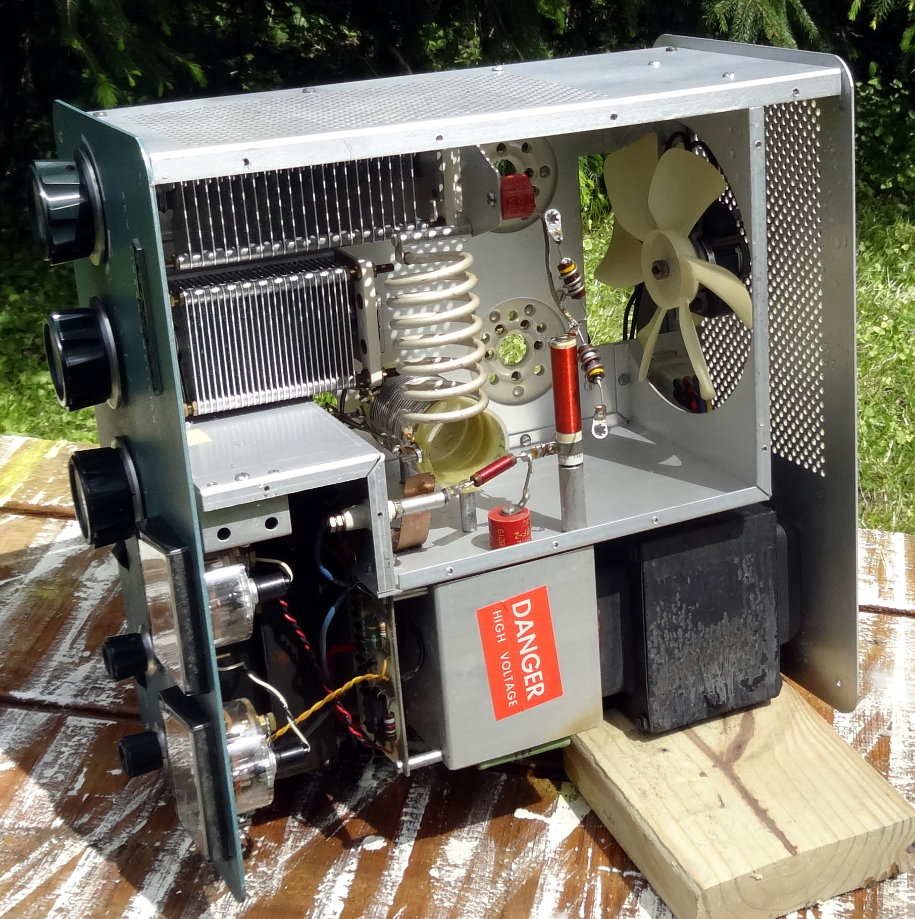
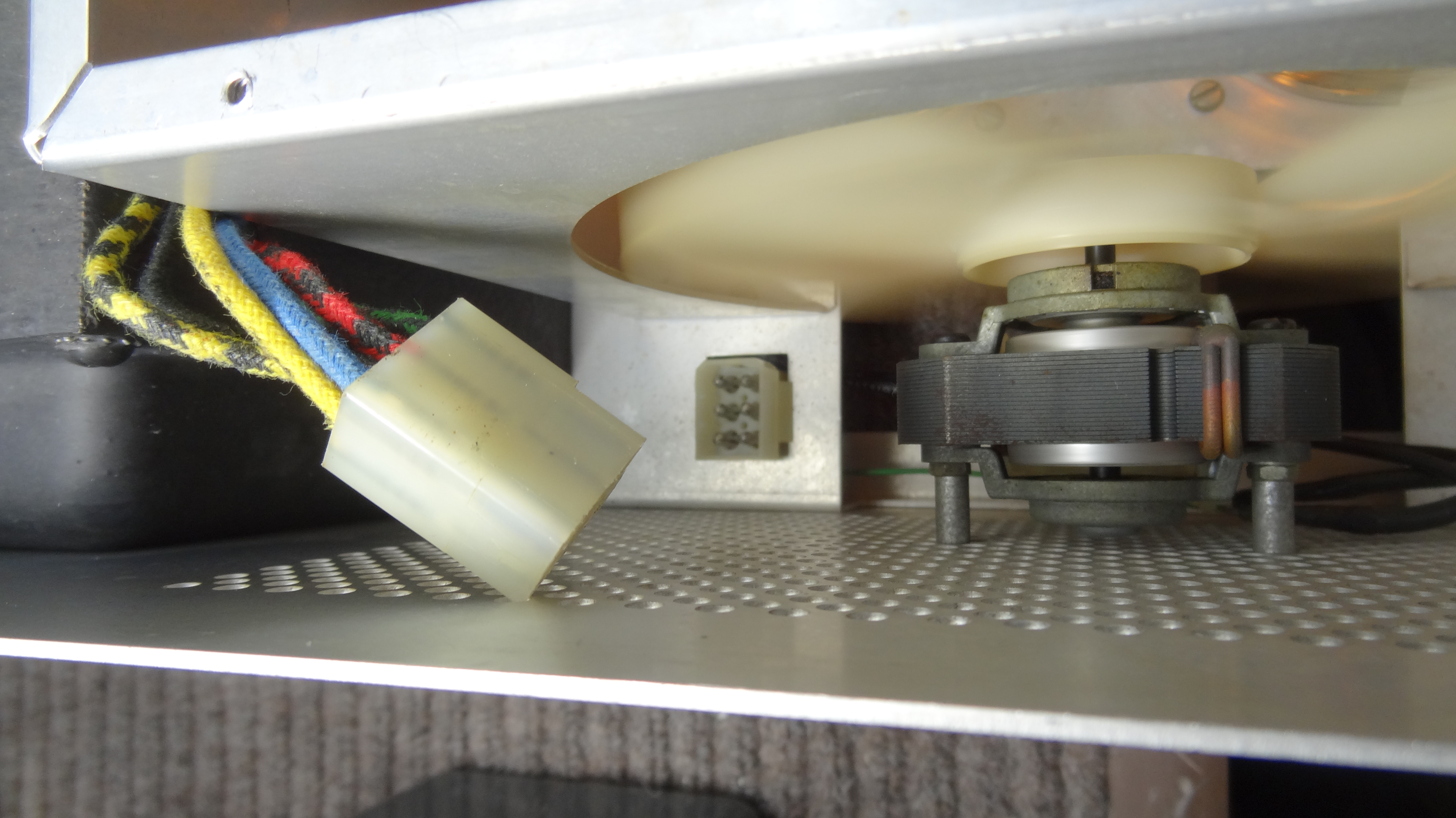 Before testing the very first thing you want to do is remove the high voltage transformer plug,
shown here. It is at the rear of the chassis between the large transformer and fan. This completely disconnects the transformer
and any possibility of high voltage being applied.
Before testing the very first thing you want to do is remove the high voltage transformer plug,
shown here. It is at the rear of the chassis between the large transformer and fan. This completely disconnects the transformer
and any possibility of high voltage being applied. Once the connector is removed and the tubes reinstalled you can proceed with a filament check. Make sure the
fan is operational and blowing air on the tubes. You can leave this "cook" for some time especially if the amplifier has
not been used for some time as it was in this case.
Once the connector is removed and the tubes reinstalled you can proceed with a filament check. Make sure the
fan is operational and blowing air on the tubes. You can leave this "cook" for some time especially if the amplifier has
not been used for some time as it was in this case.Having passed the turn-on test minus the high voltage I went on with the rest of the restoration. I had purchased the soft-start, meter and high voltage diode board, and the capacitor board kit from Harbach. So installing those items and other mods proceeded.
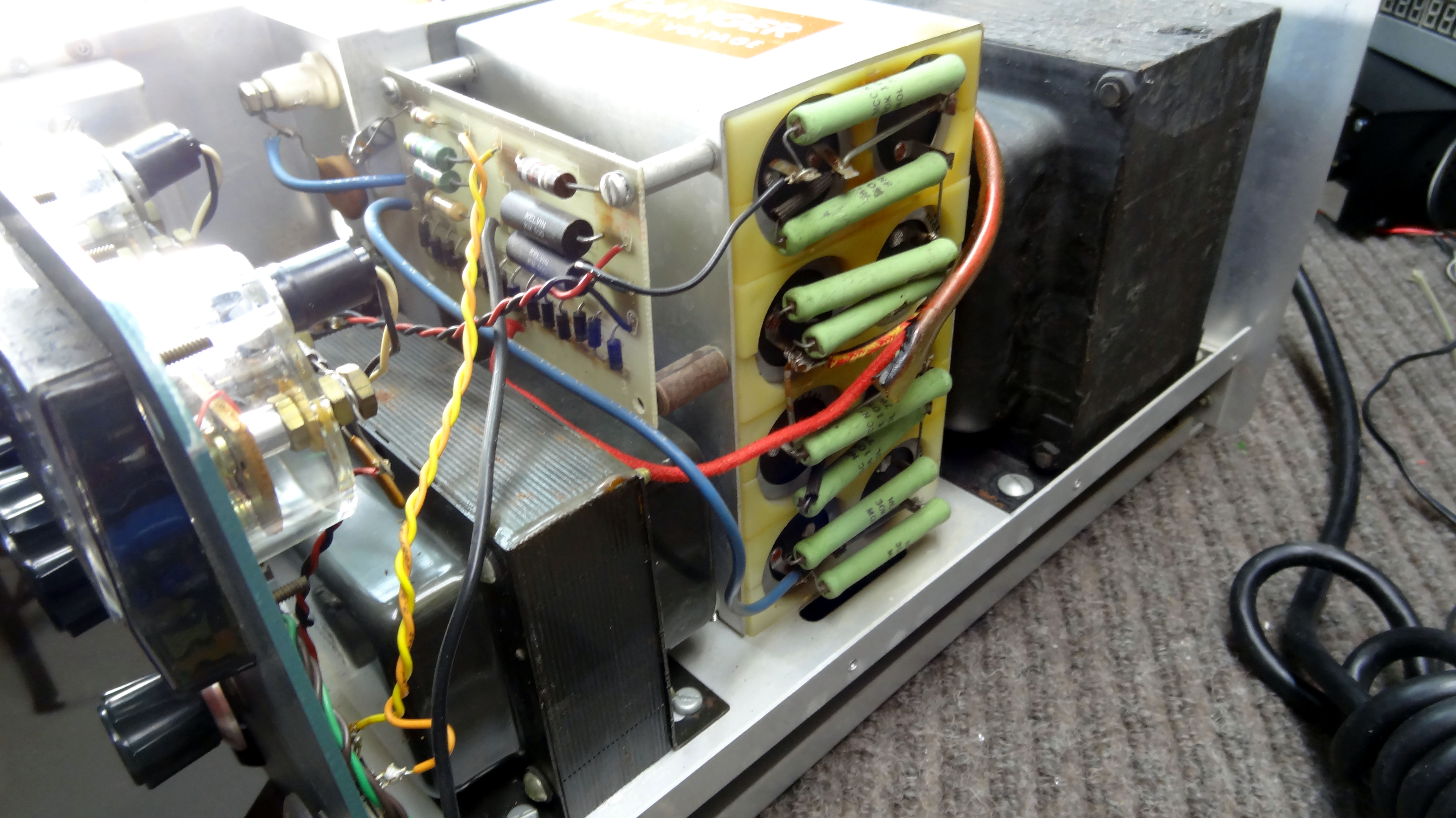 Photo of the original high voltage and meter board and filter capacitor bank.
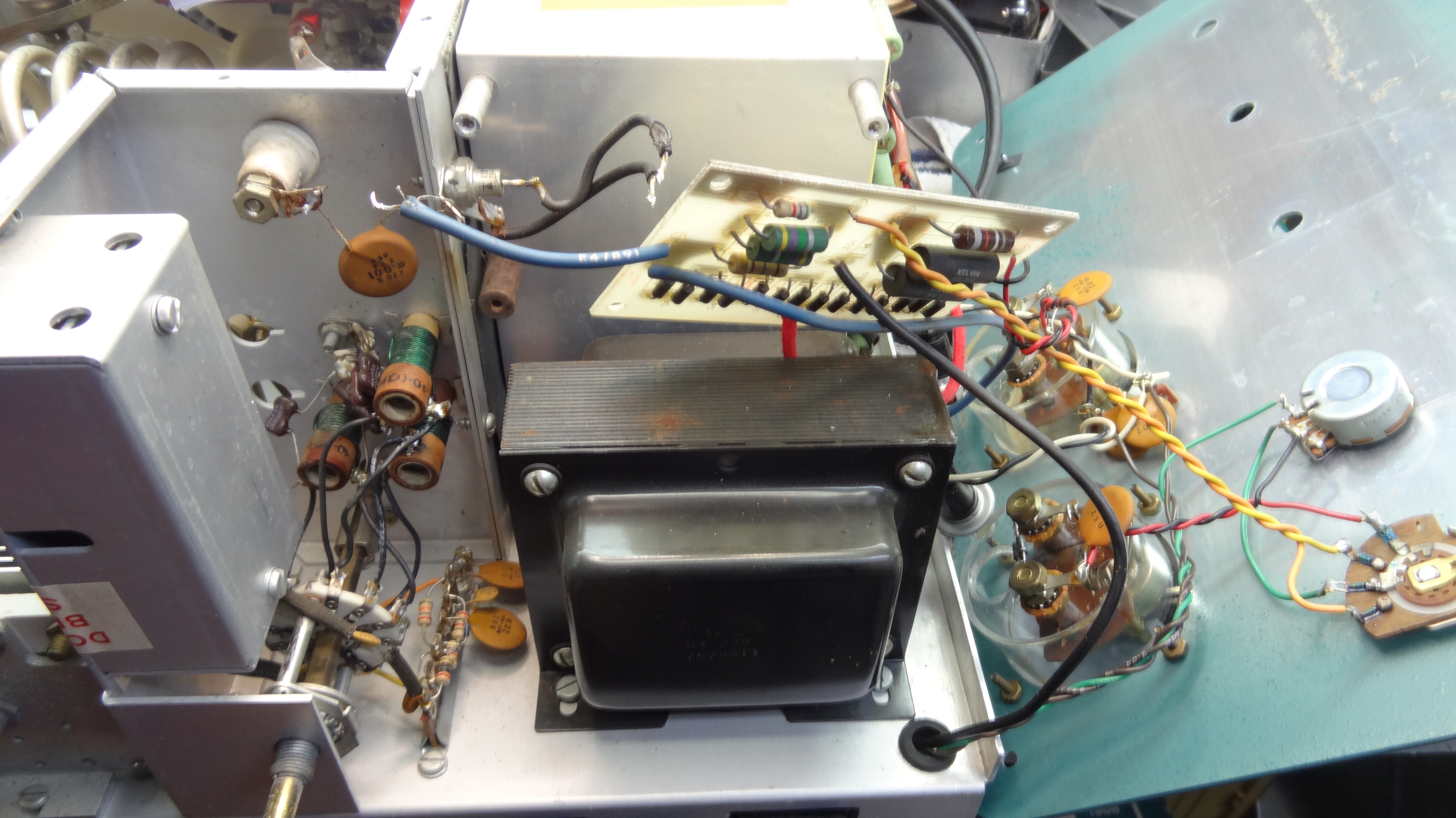 Removing the old meter/high voltage board.
 More photos of board removal.
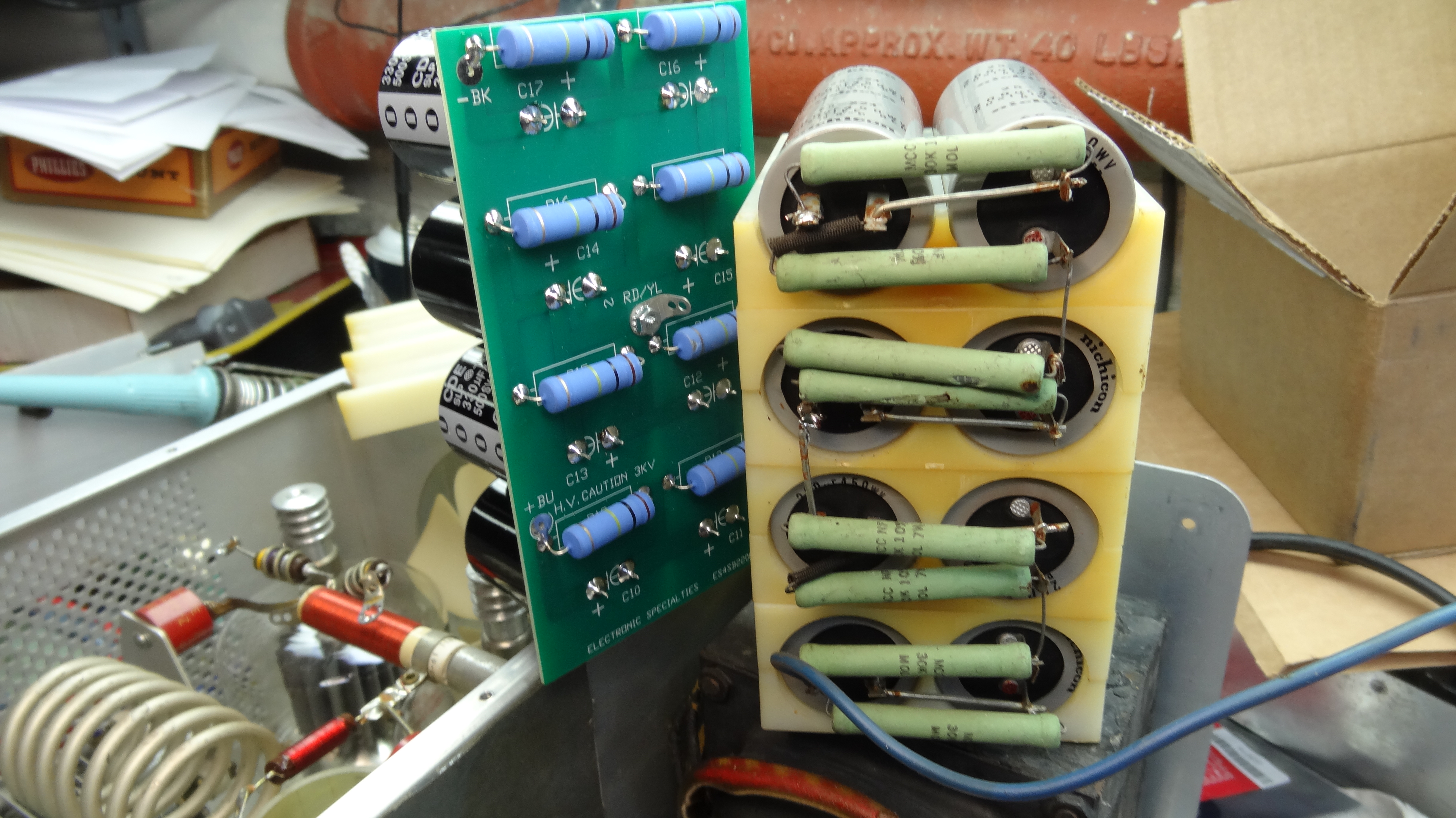 Old capacitor bank remove alongside the newly built bank. The bleeder resistors are a higher value creating
less heat.
Old capacitor bank remove alongside the newly built bank. The bleeder resistors are a higher value creating
less heat.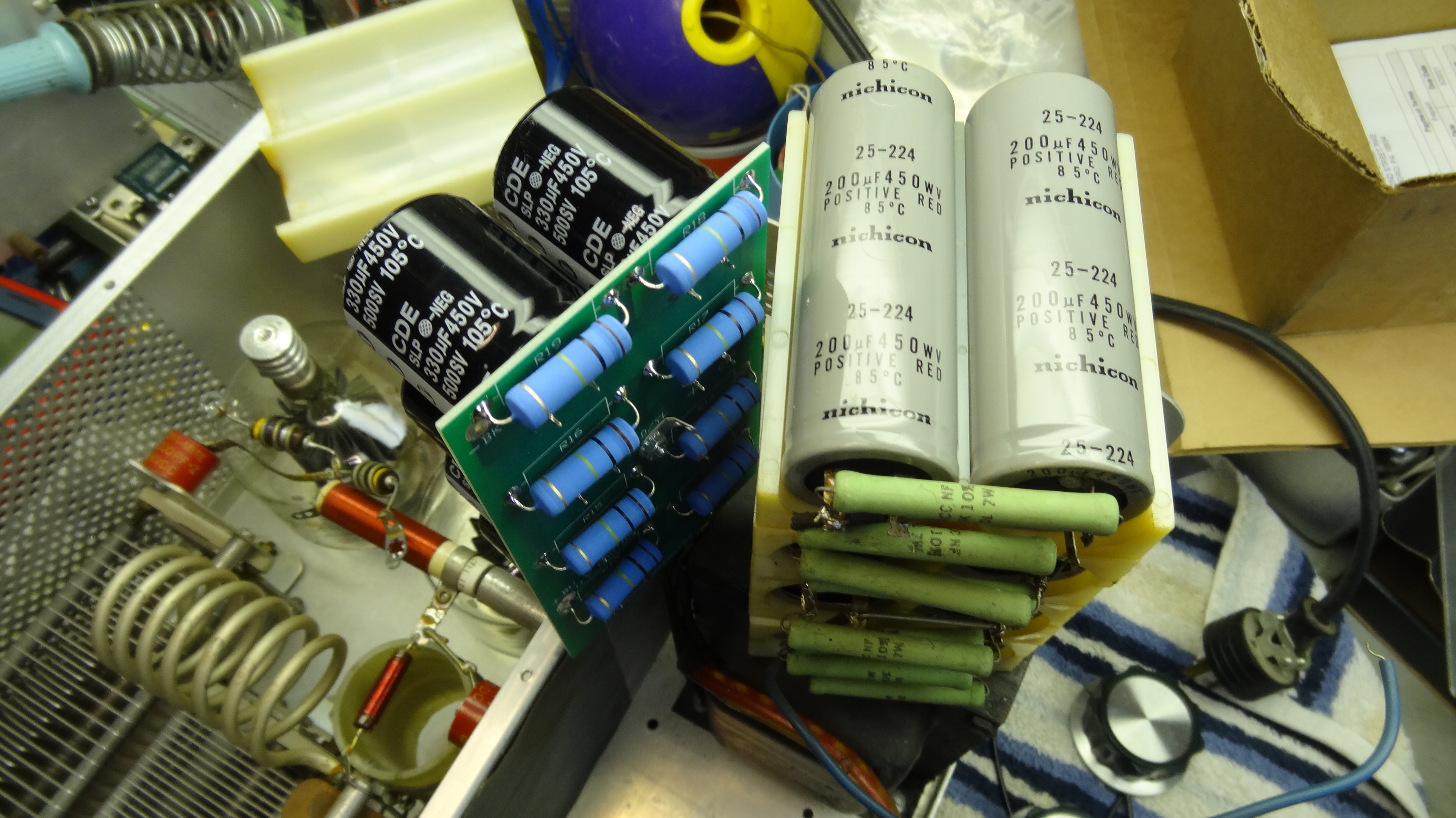 Comparison of capacitor banks. Old bank was each capacitor 200uf@450V 85C and new is 330uf@450V 105C, a significant
improvement.
Comparison of capacitor banks. Old bank was each capacitor 200uf@450V 85C and new is 330uf@450V 105C, a significant
improvement. 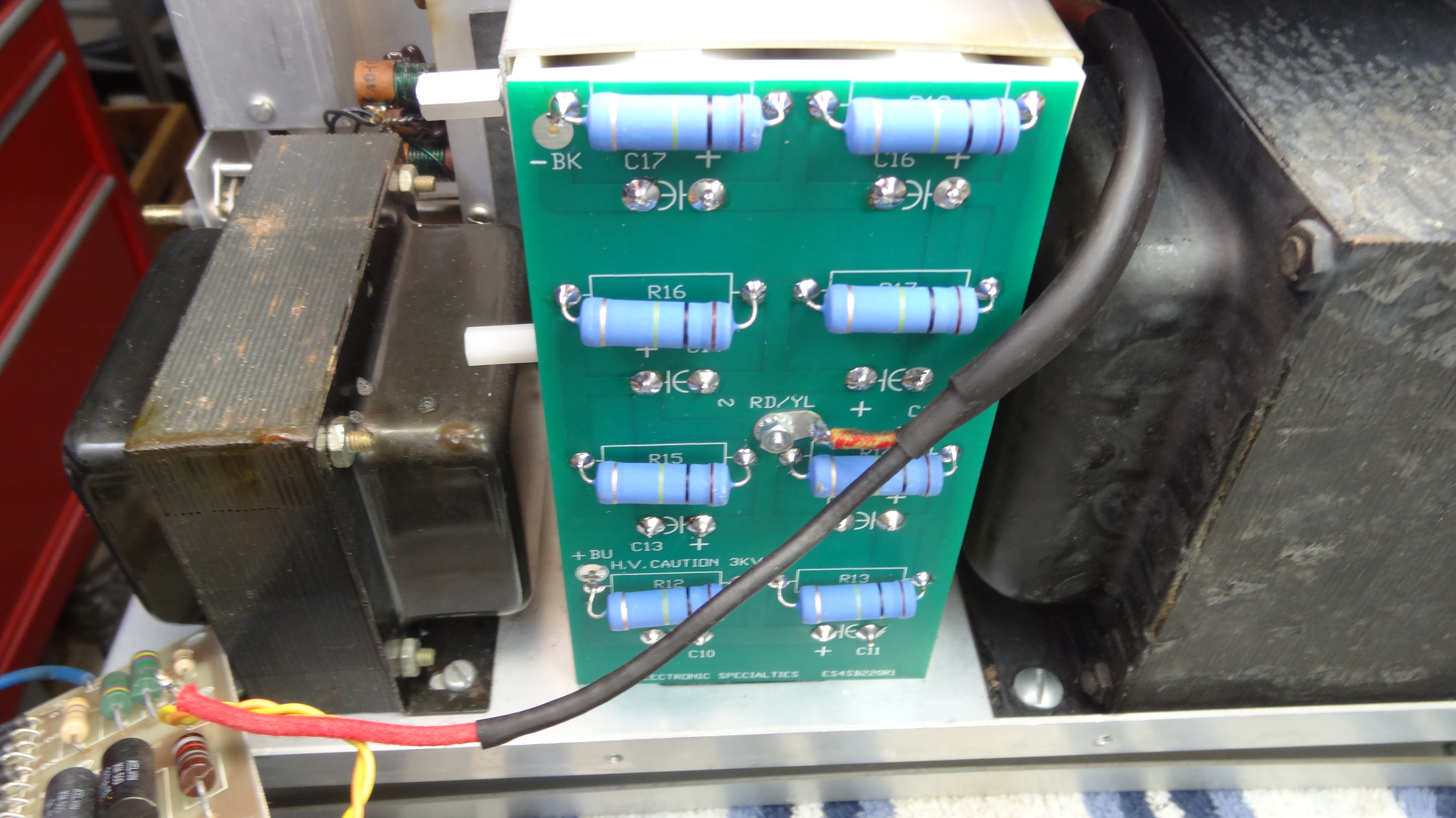 New capacitor bank installed
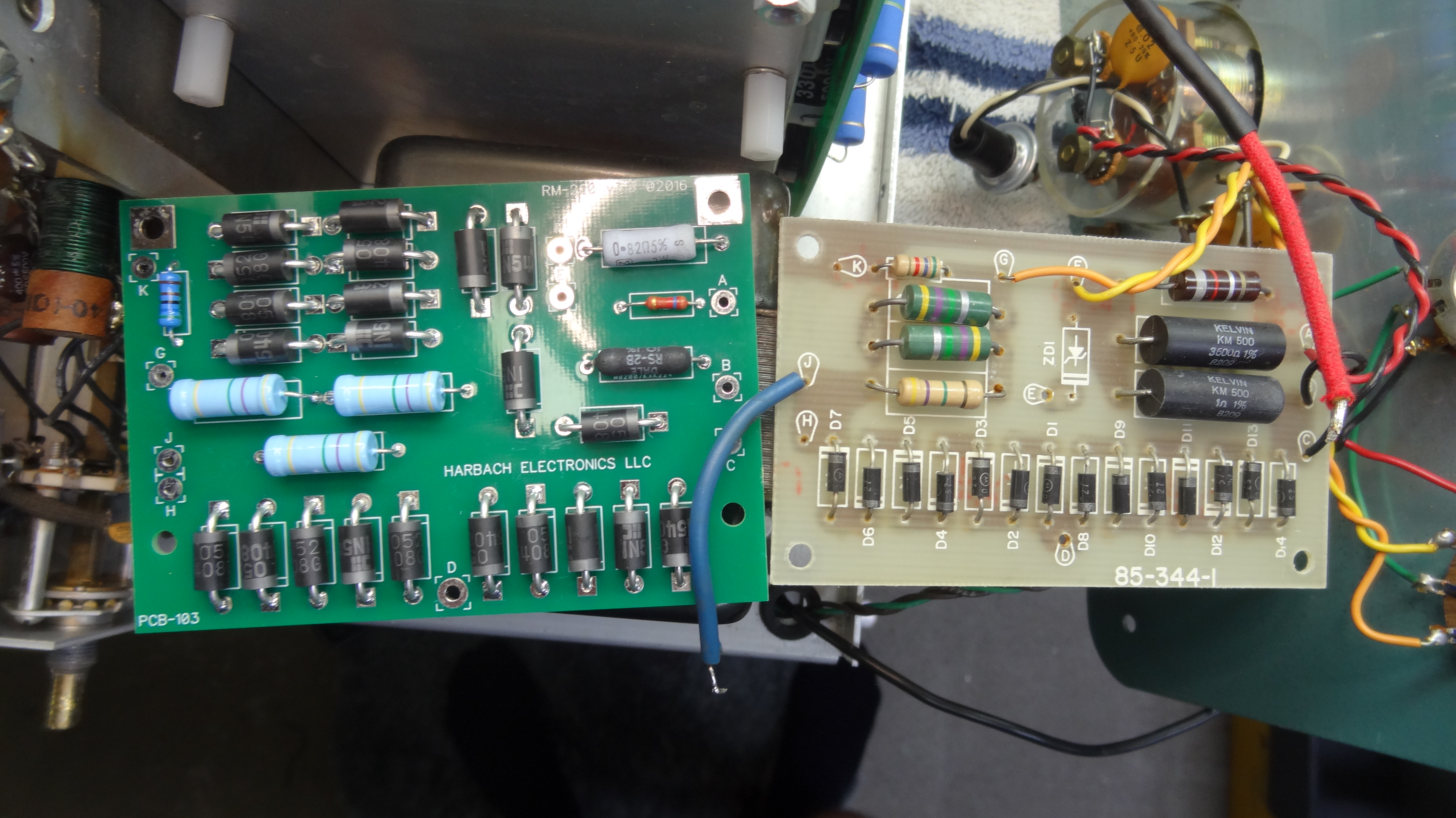 Comparison of (left) new meter, HV rectifier, bias board and old board.
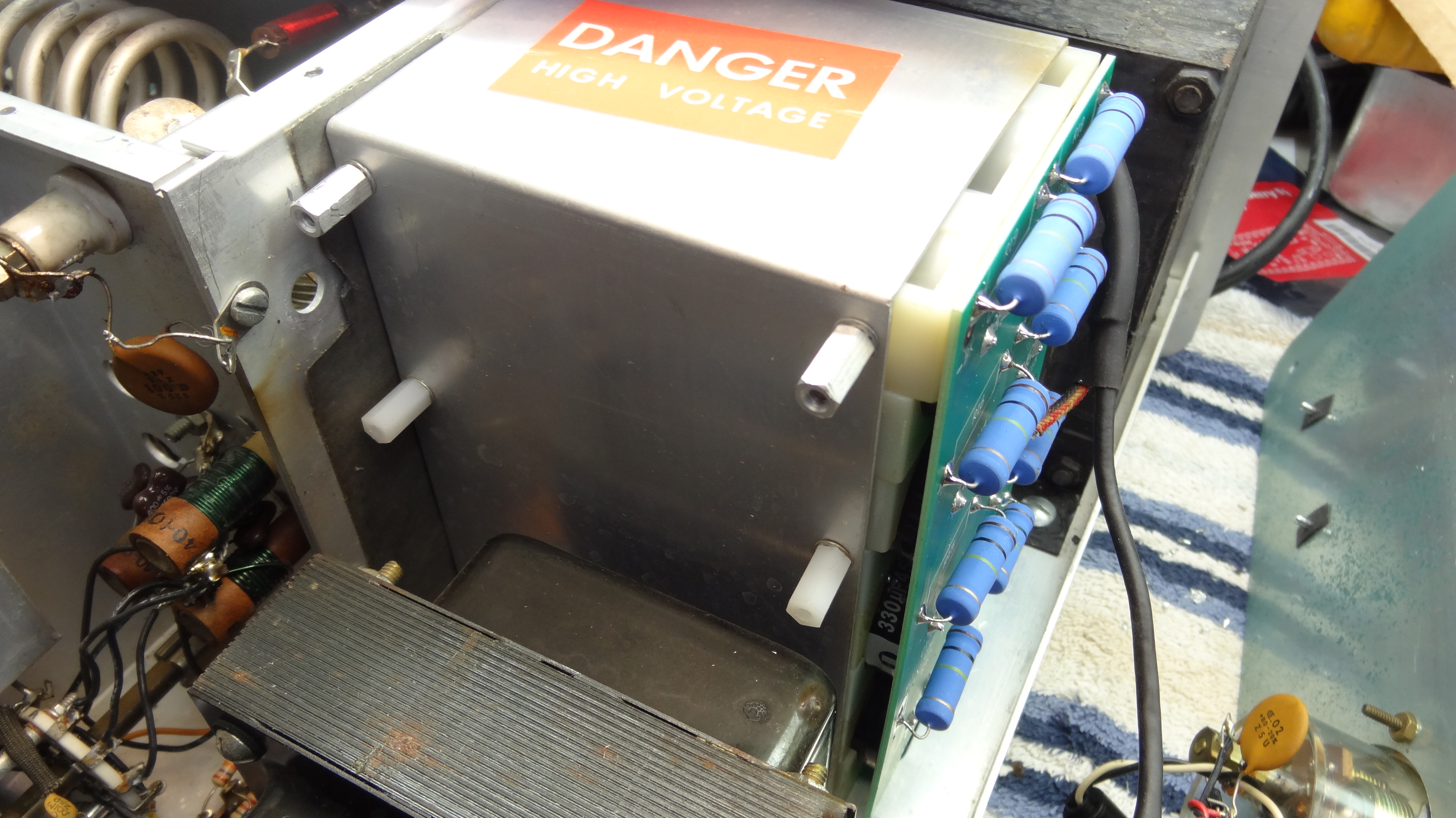 Ready for new board installation.
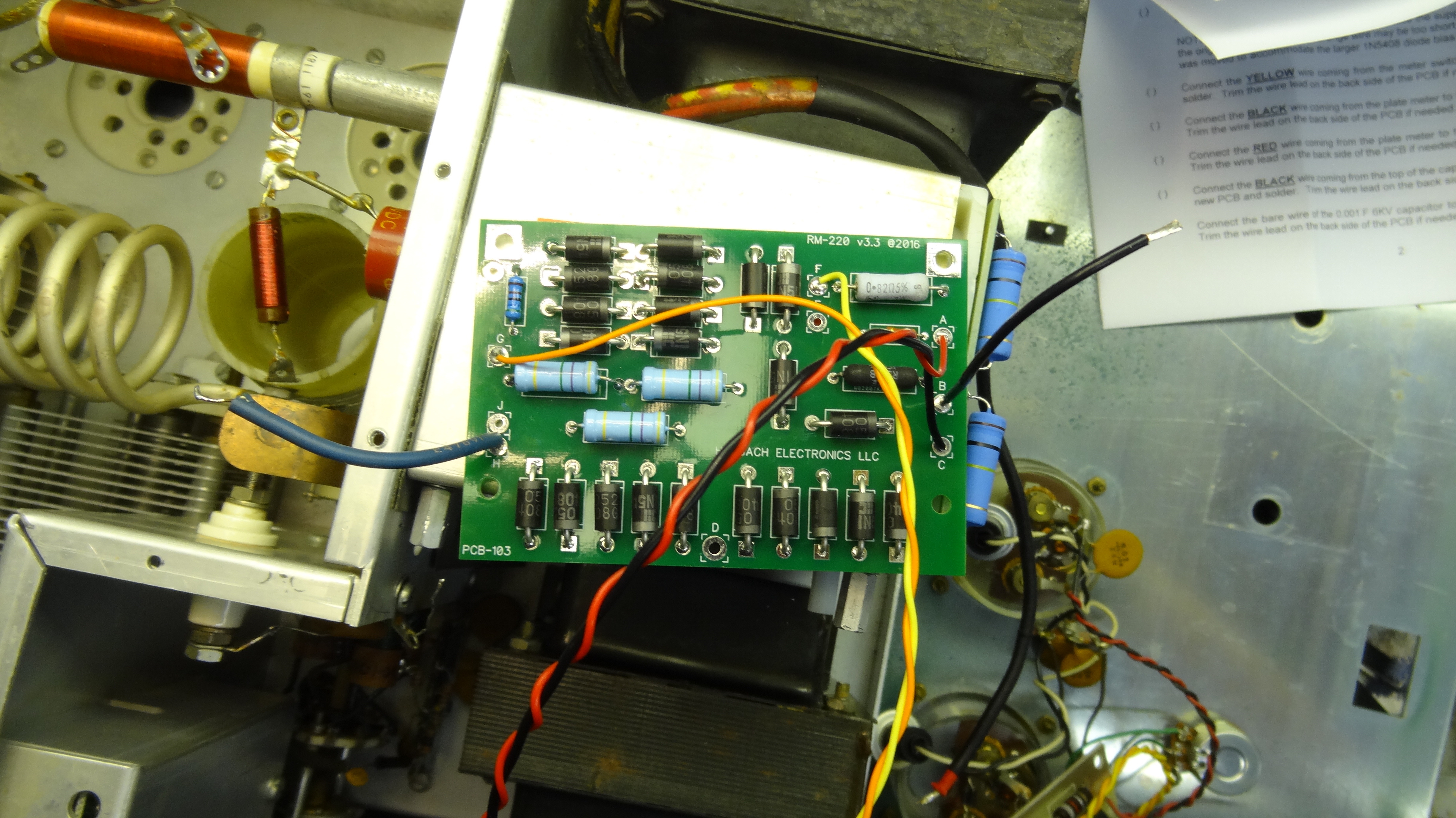 New board being wired before installation. Easier that way!
 Adding a fuse in the high voltage line. Holder is mounted on a ceramic stud.
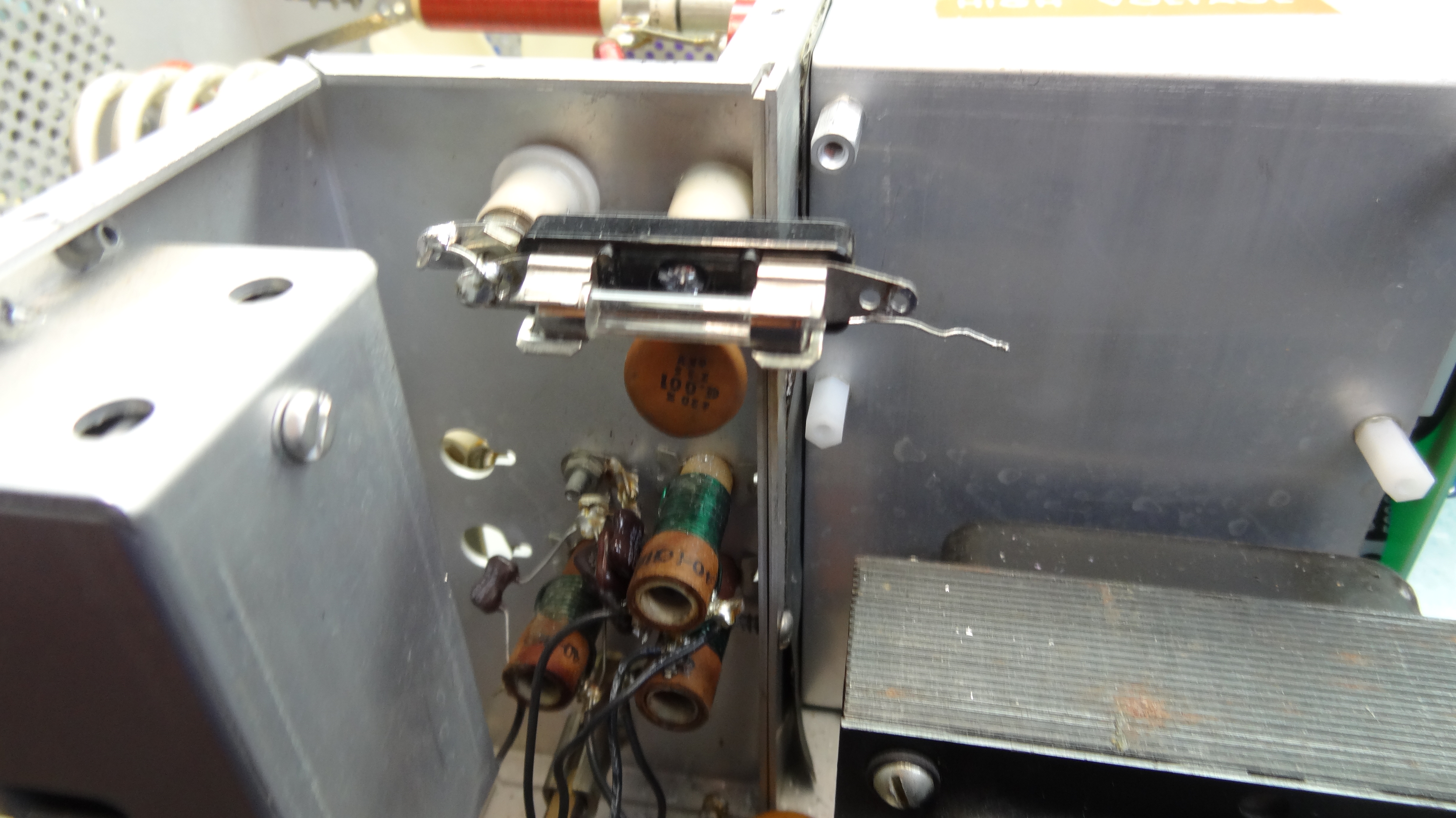 Clearances are sufficient for 3KV.
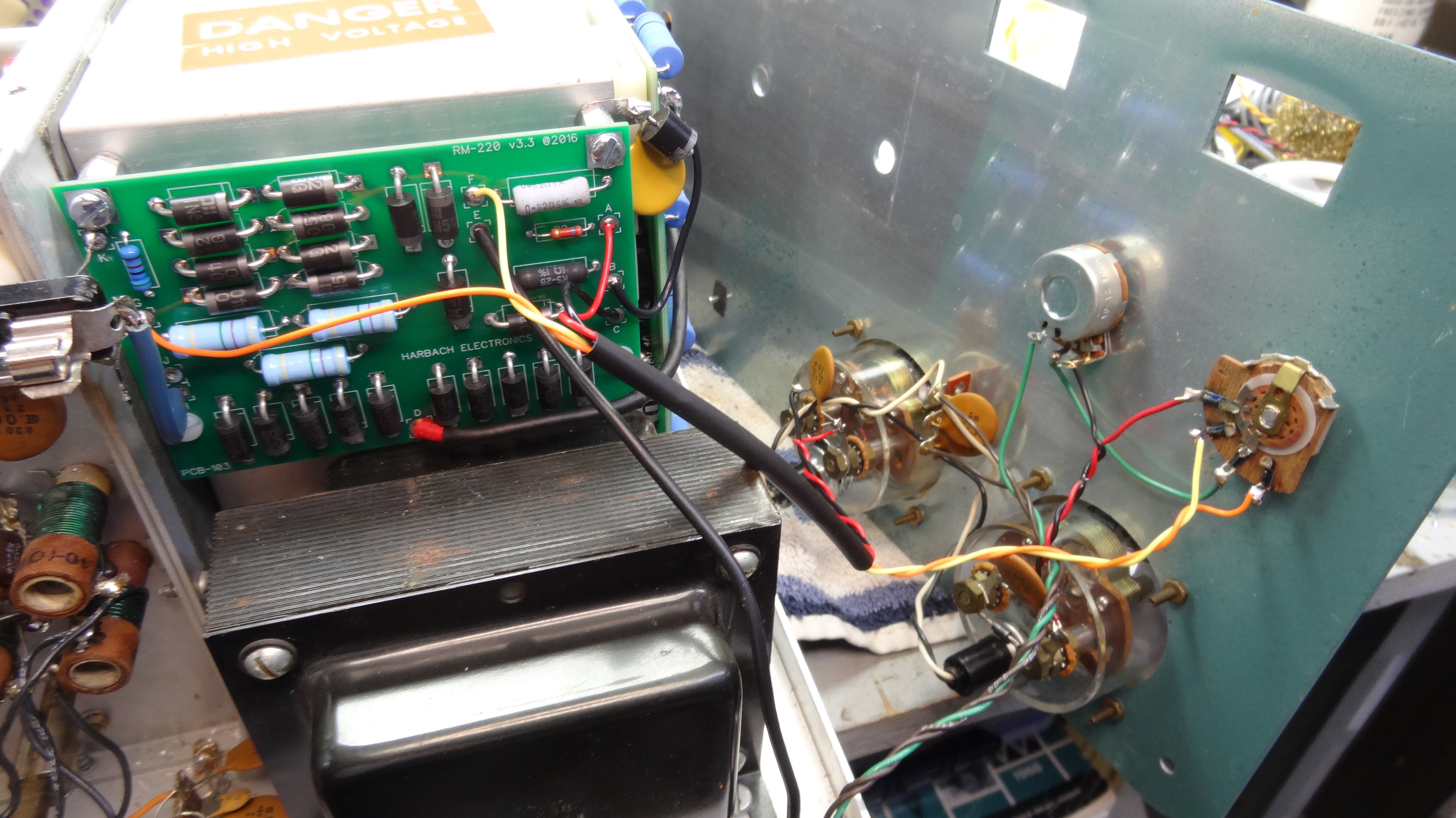 Mounting the new board.
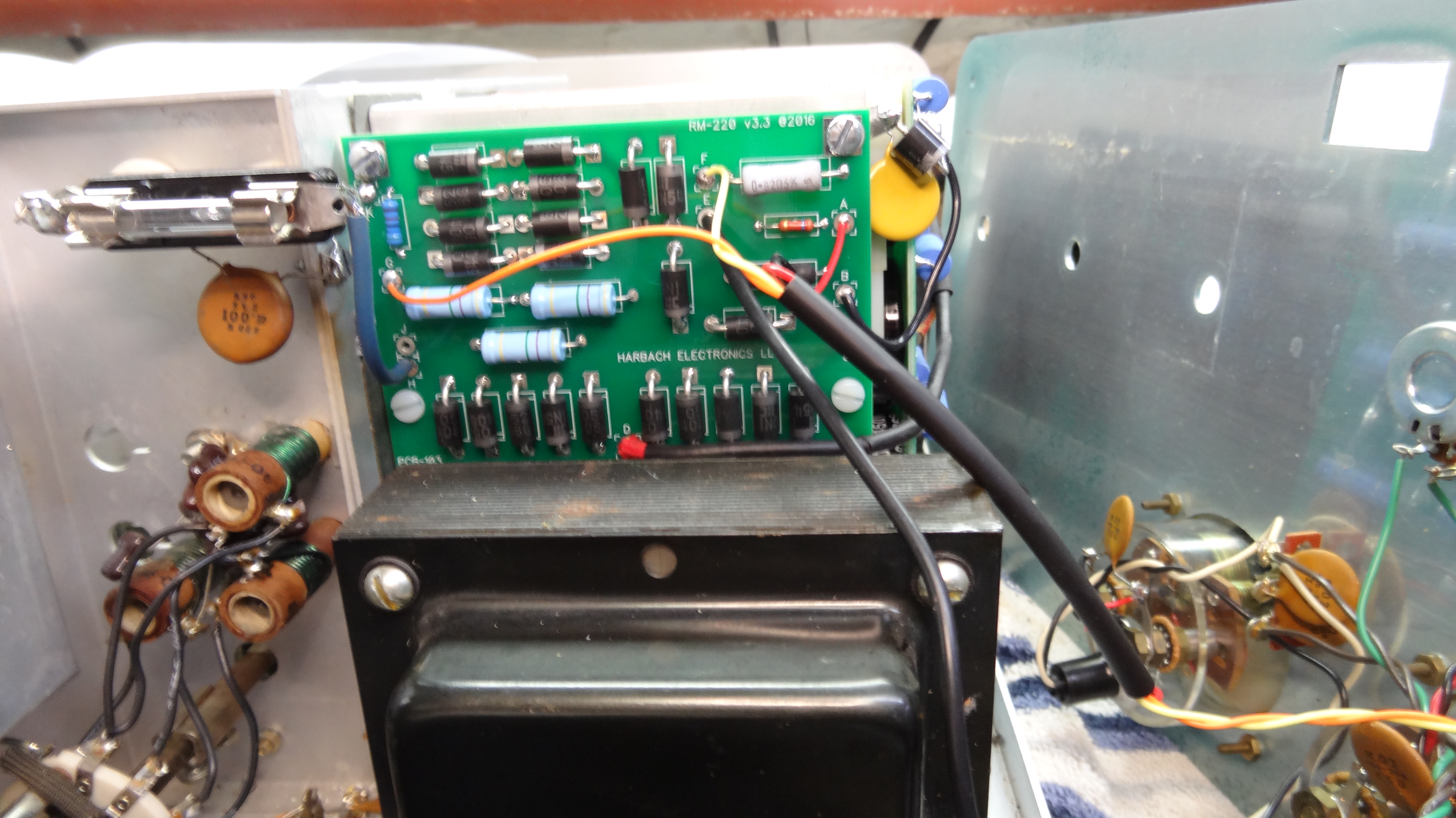
 Mounted new board and capacitor bank. Note added protection diode and bypass to ground.
 Fuse connected to high voltage board.
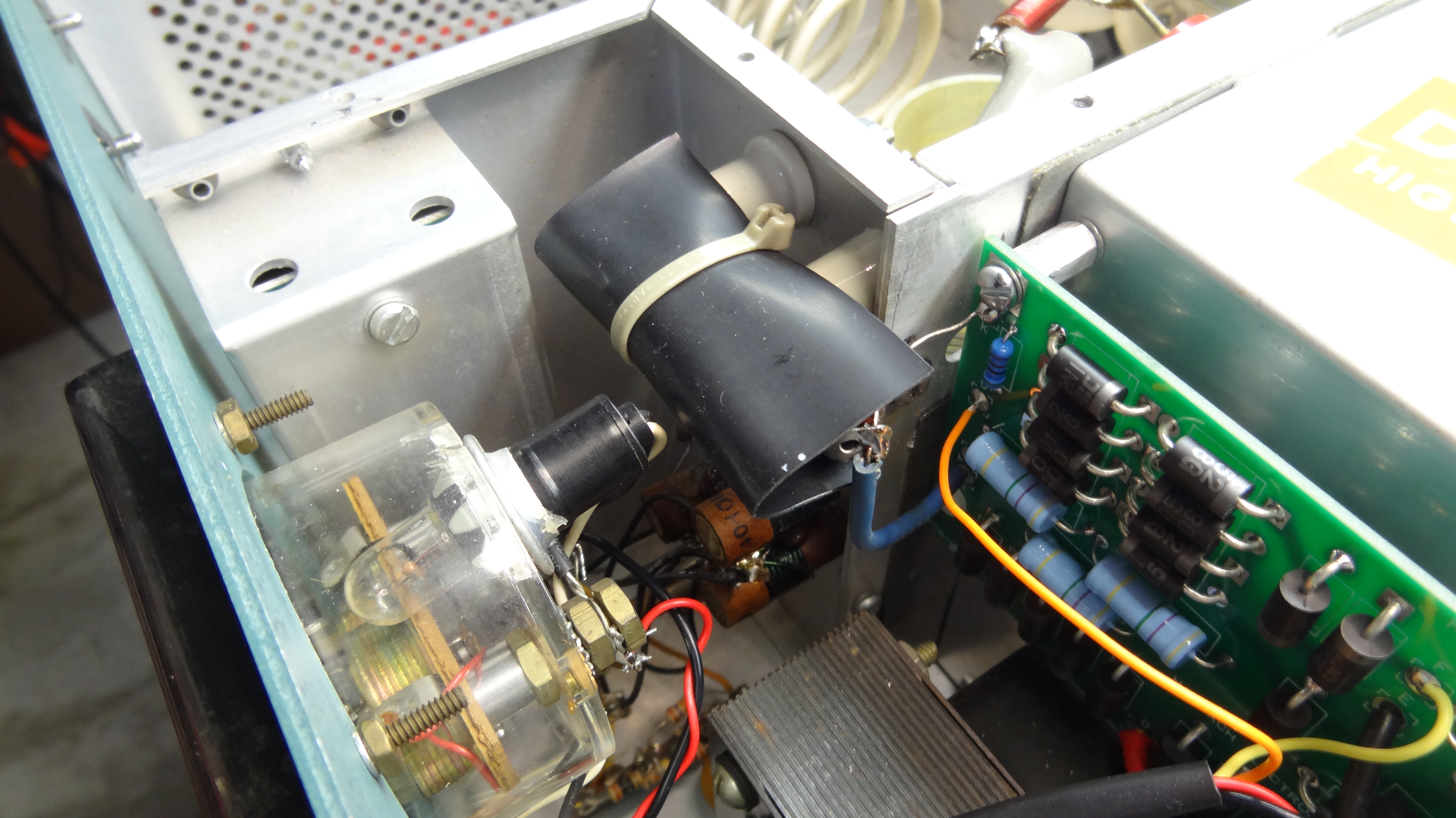 Fuse covered for protection.
 Blown fuses (see text)
I felt it was important to protect the high voltage supply and the amplifier in general by adding a series (glitch) resistor and a fuse in the high voltage line as shown in the photos. I had a problem with arcing due to a mod I had made in the project and in the end that turned out to be a blessing. After blowing several 1A fuses as shown in the photo, blacked out inside, I discovered where the problem was. This did show me that the fuses work and nothing was damaged. I also discovered that the fuse needs to be wrapped with black tape over the glass and just a little of the metal ends. This protects the glass from flying should the fuse blow up as it did in one case as shown in the photo with only the metal ends left. This is VERY IMPORTANT as the glass could dangerously fly out. NEVER run the amplifier without the fuse taped and covered.
The safety shorting strap was removed. For me this was a good idea as it left room for the glitch resistor and in my experience the high voltage bleeds to nothing in less than a minute and I am careful to never get anywhere near the high voltage. If you were to (stupidly) turn on the amplifier with the cover off and safety strap installed it would be a direct short on the high voltage. With the fuse installed this probably would not cause a problem but without a fuse it would most certainly damage something in the high voltage supply before hopefully blowing the rear panel circuit breaker. A much better way for Heath to have done this albeit more expensive would be to both disconnect the primary to the high voltage transformer and short the high voltage to ground. Also keep in mind that the shorting strap only protected the RF cage leaving lots of other places where you could come in contact with high voltage in the amplifier with it turned on.
This is a good time to give a warning about working around high voltage that can cause injury or kill. DO NOT operate this amplifier with the covers removed unless you are acutely aware of the rules of working around high voltage. Never allow your hands or any part of your body to come anywhere close to anything inside the chassis. NEVER use a meter without a high voltage probe to measure voltages above 800 volts or whatever maximum is marked on the meter. I would also recommend wearing safety glasses. There are other rules about working around high voltage that you can read in the manual. BE CAREFUL!!!
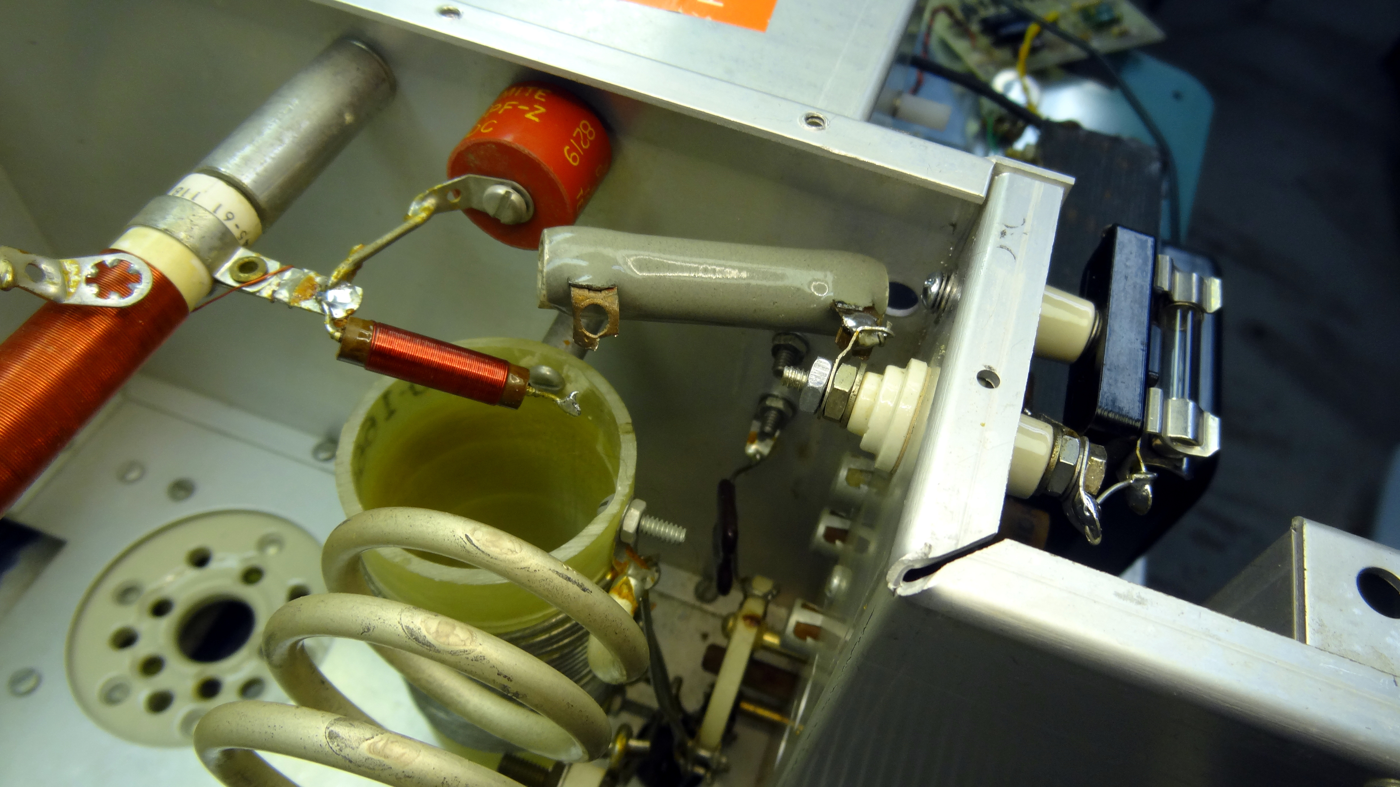 20 ohm high voltage series Glitch resistor added.
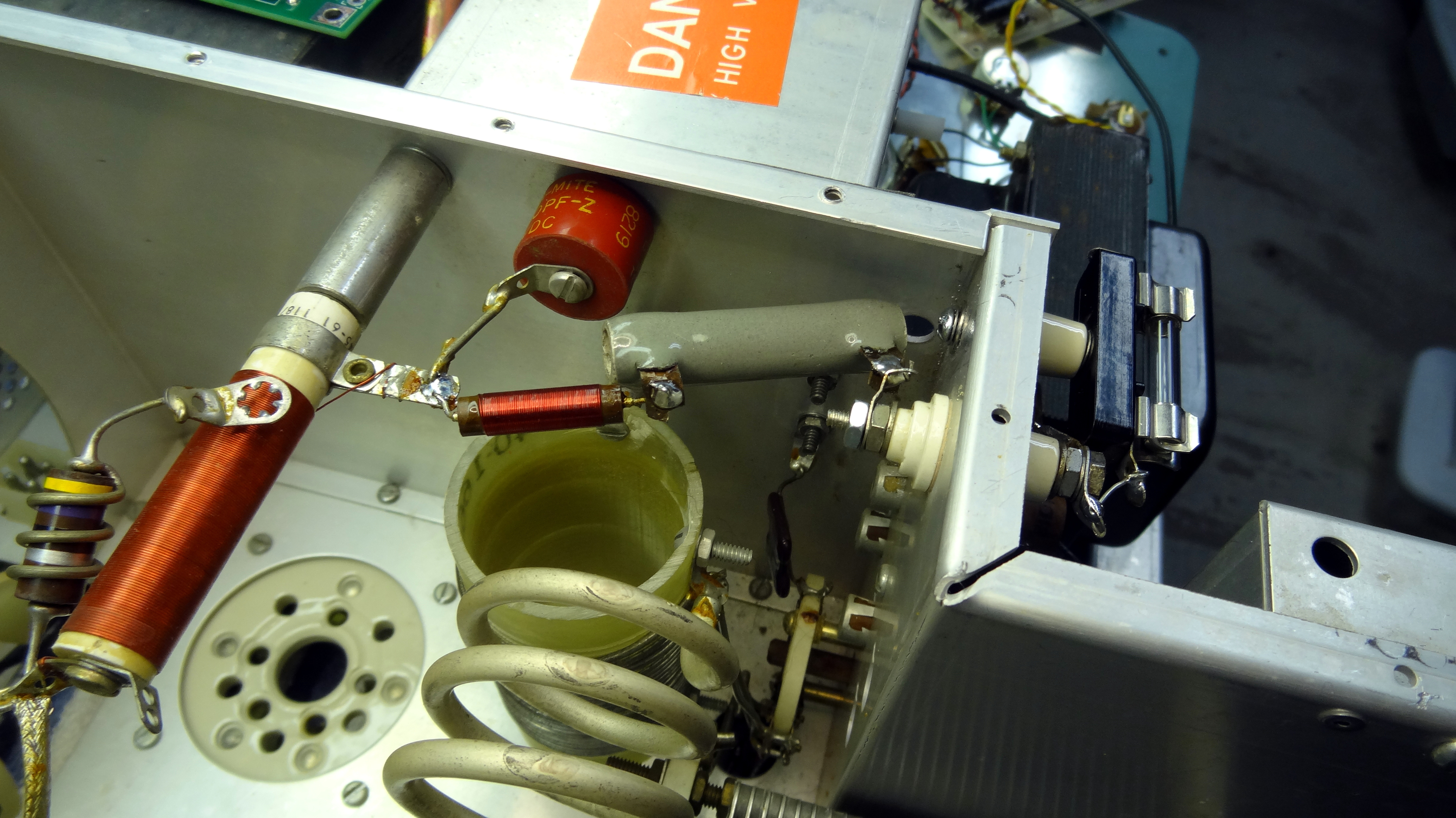 Note that the shorting strap has been removed (see text).
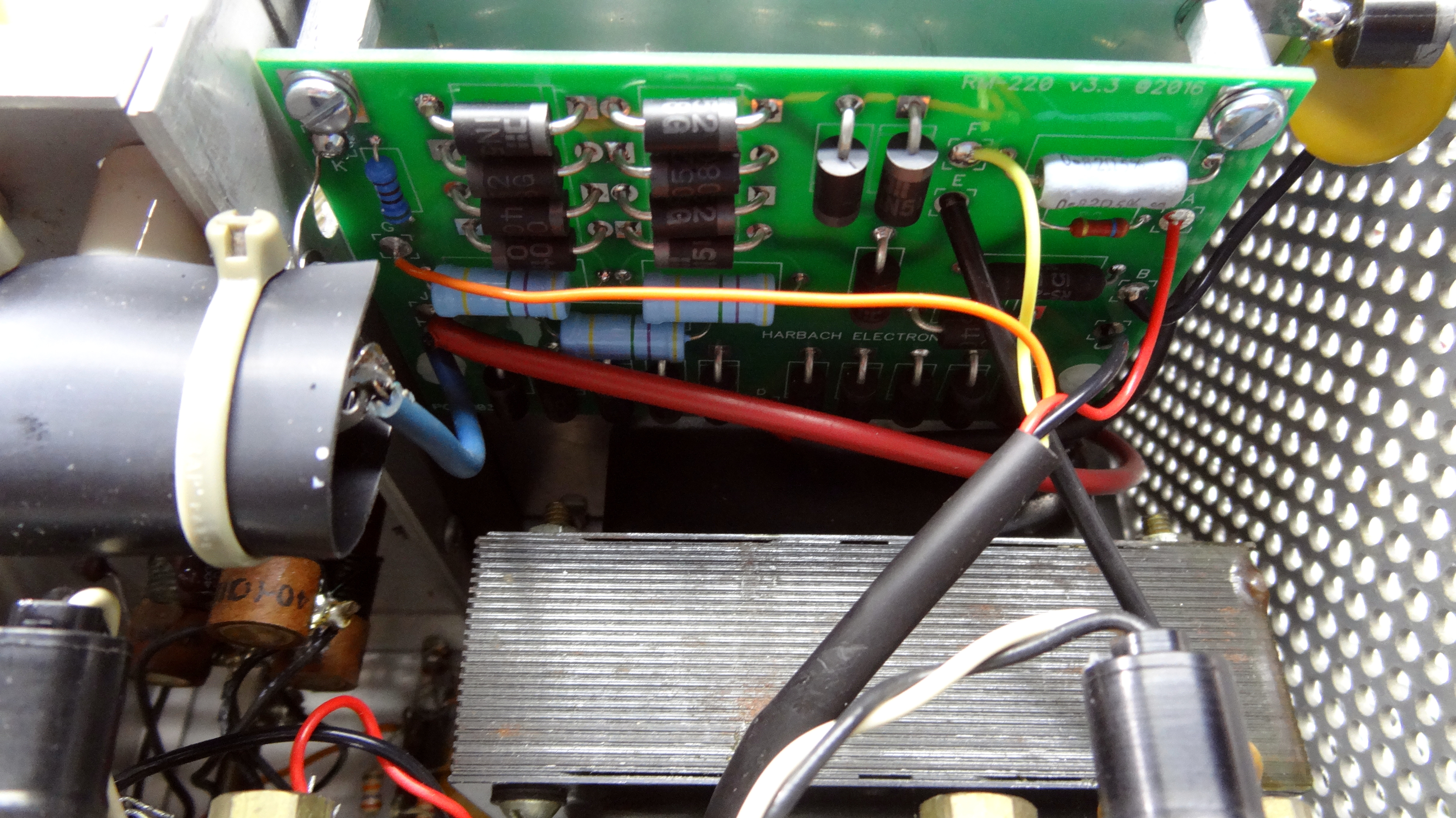 Another photo of the new meter/bias/HV board installed.
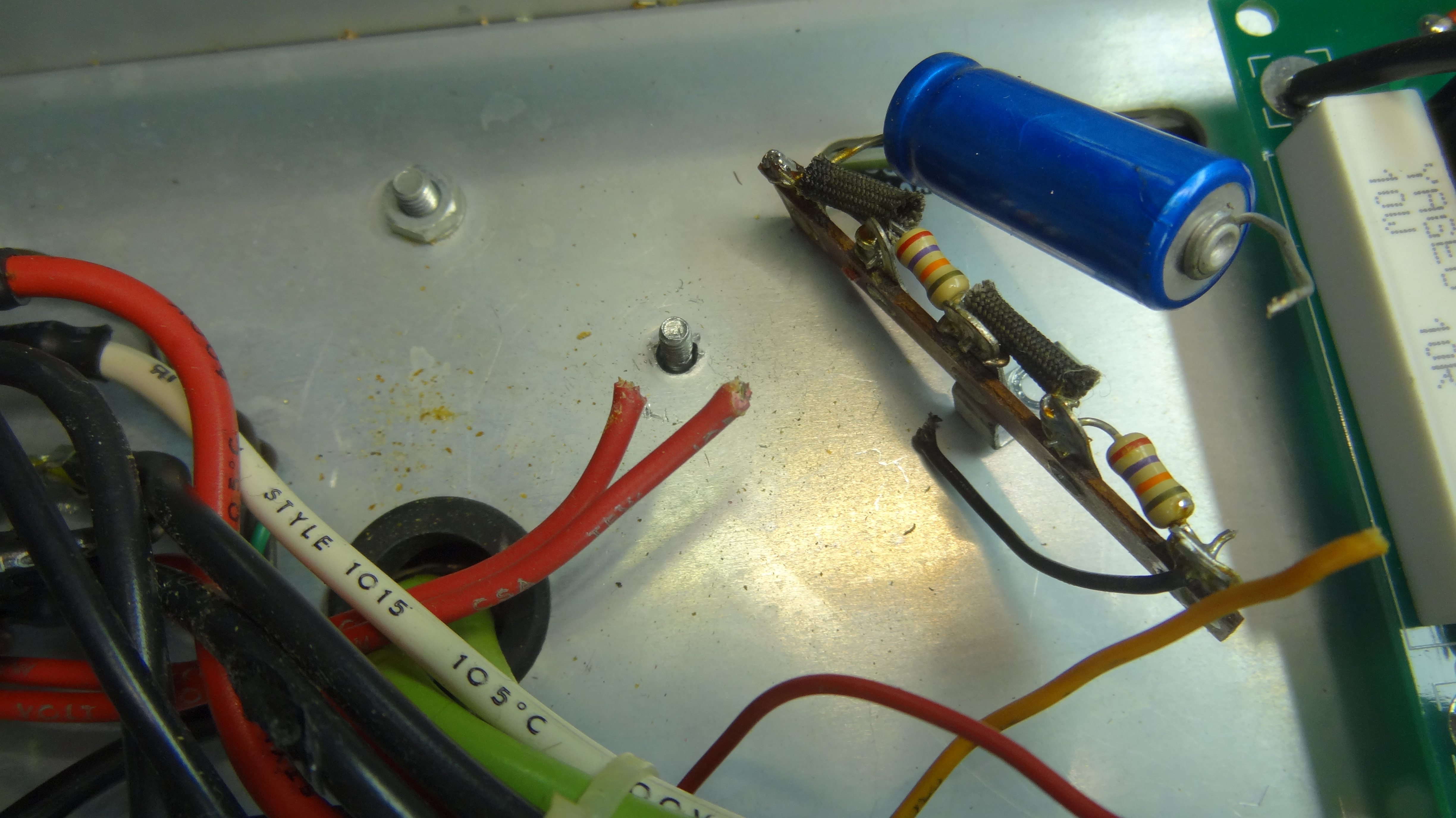 Removal of old bias circuit strip. Red leads are transformer AC for bias.
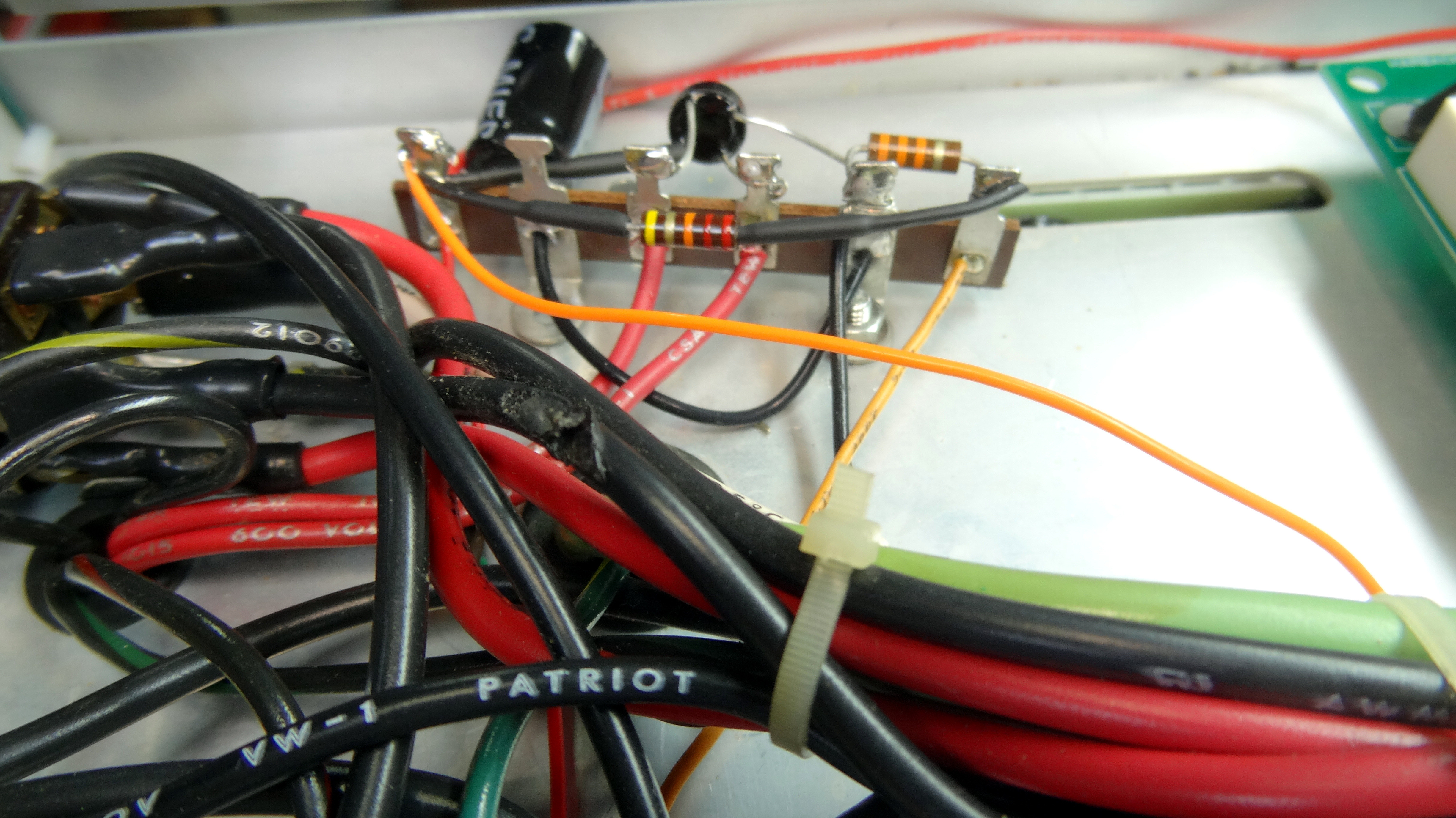 New terminal strip and parts installed for bias. new bridge rectifier from soft-start kit.
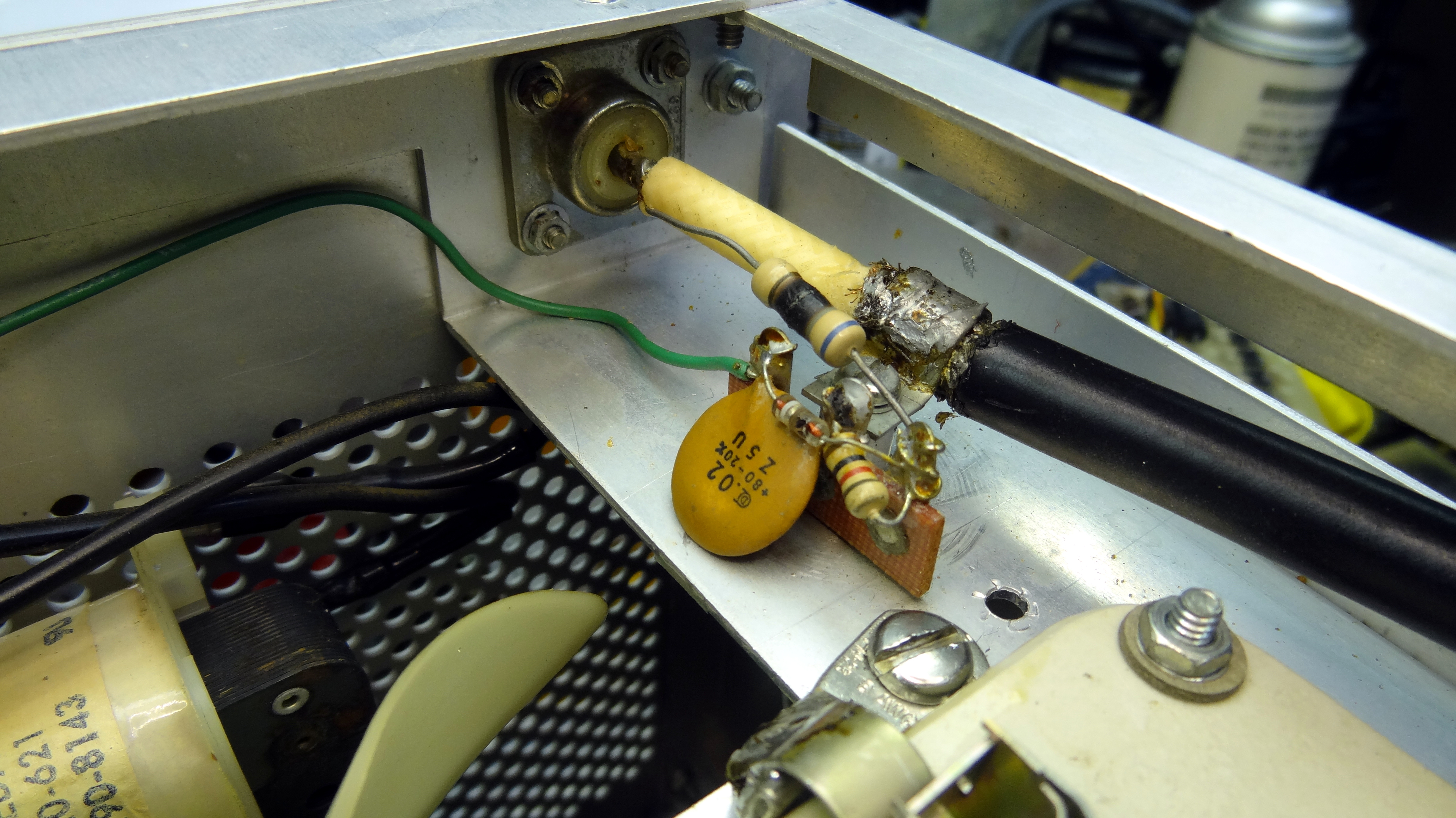 RF output showing burned resistor. Resistor replaced and cable replaced with teflon coax.
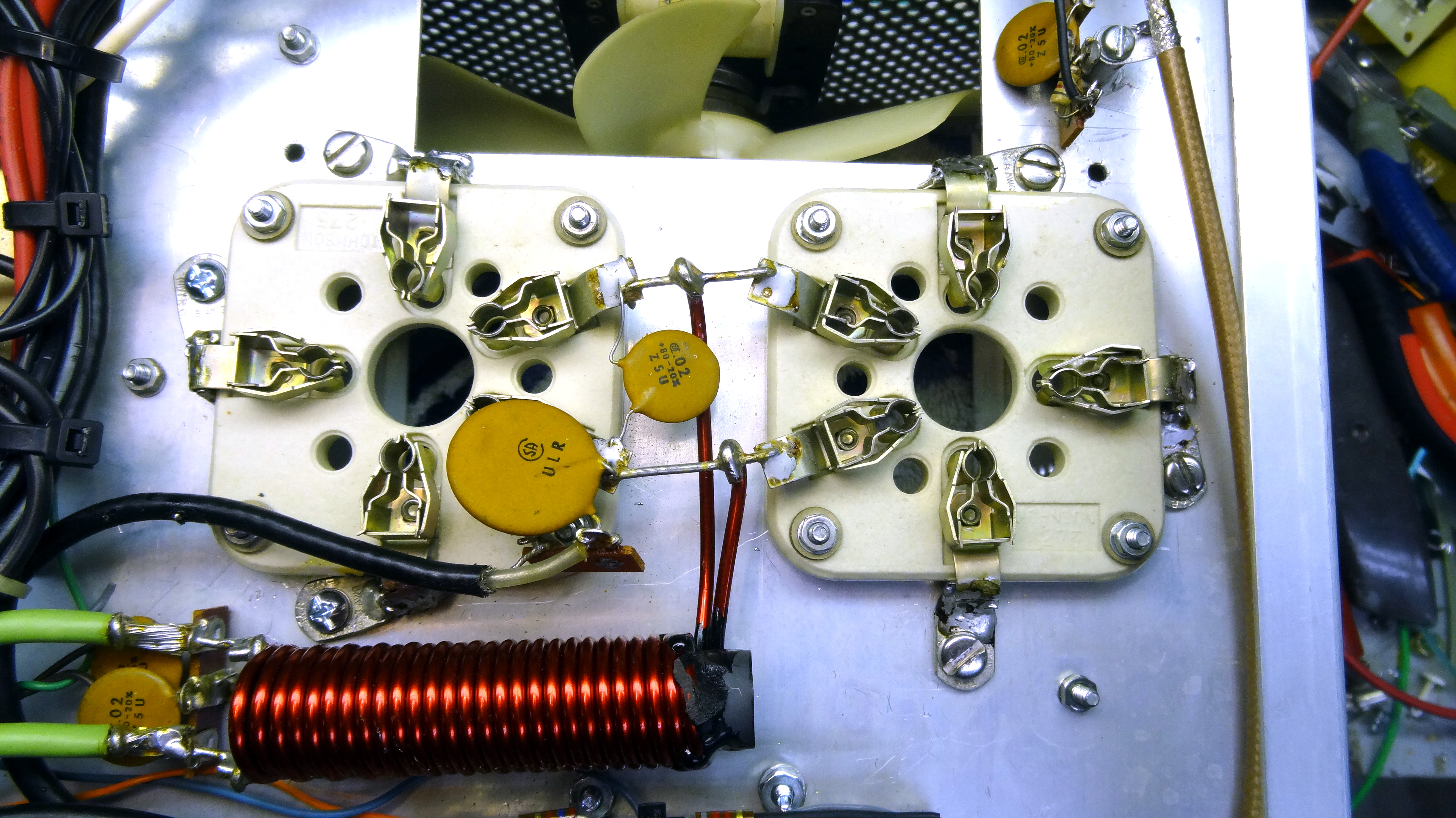 All grid circuitry removed and grids directly grounded. Three pins to ground per tube. New output coax shown to
right.
All grid circuitry removed and grids directly grounded. Three pins to ground per tube. New output coax shown to
right.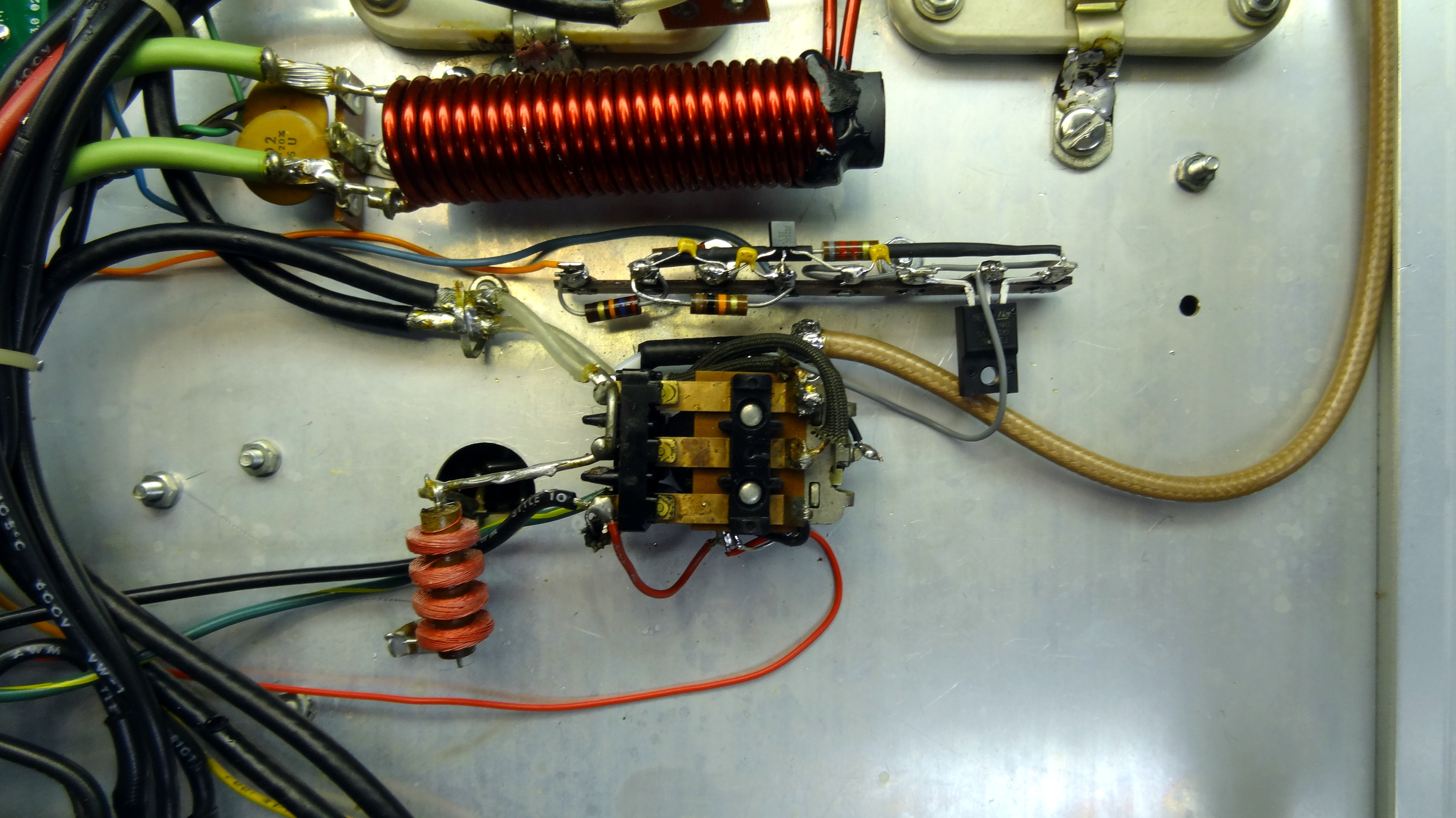 Showing new coax from relay to output jack. Homebrew soft-key terminal strip just above the relay.
 Shown in the photo above between the relay and the filament choke is the homebrew soft-key circuit. It uses a high voltage FET to switch the relay using the 120V bias voltage. Bias voltage divided down is used to key the FET via a bipolar transistor. The voltage on the back panel keying RCA jack is less than 6 volts and about 1-2ma of current to key when grounded. This makes it completely safe for any transceiver. Importantly you do need to add back to back diodes across the relay coil to protect the FET. The relay is kind of hokey for switching 1500 watts of RF but it works so I did not change it out for this project. Some mods use a vacuum relay replacement but that is probably overkill unless you have one in your junk box. Changing the relay would also probably require adding a 12 or 24 volt supply voltage to operate the relay.
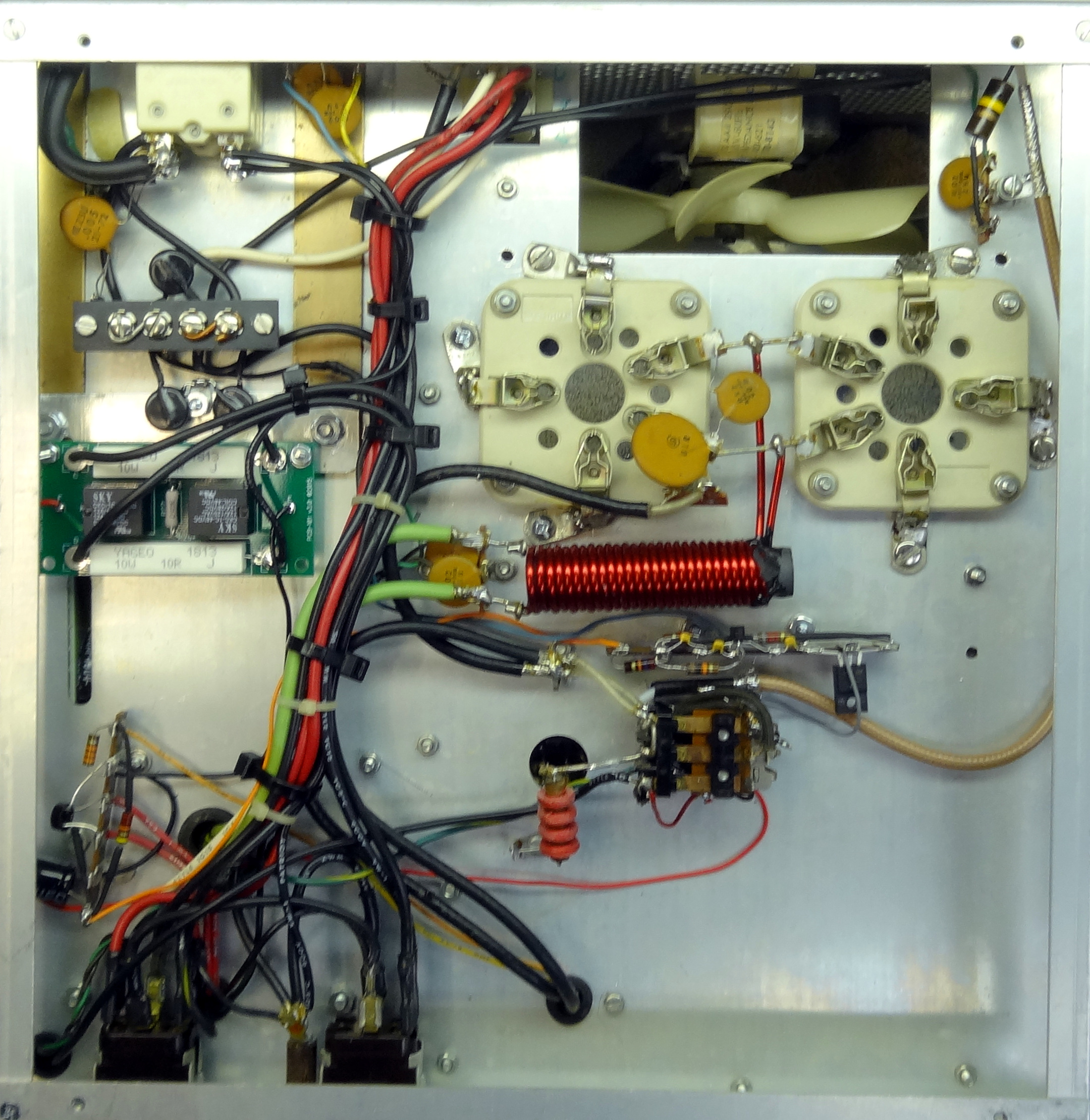 Bottom view with most of the mods installed.
 Because the amplifier in my case is to be run on 120V the neutral side circuit breaker was jumpered out. Make sure your
shack and the amplifier are wired properly and this is really the neutral side!
Because the amplifier in my case is to be run on 120V the neutral side circuit breaker was jumpered out. Make sure your
shack and the amplifier are wired properly and this is really the neutral side!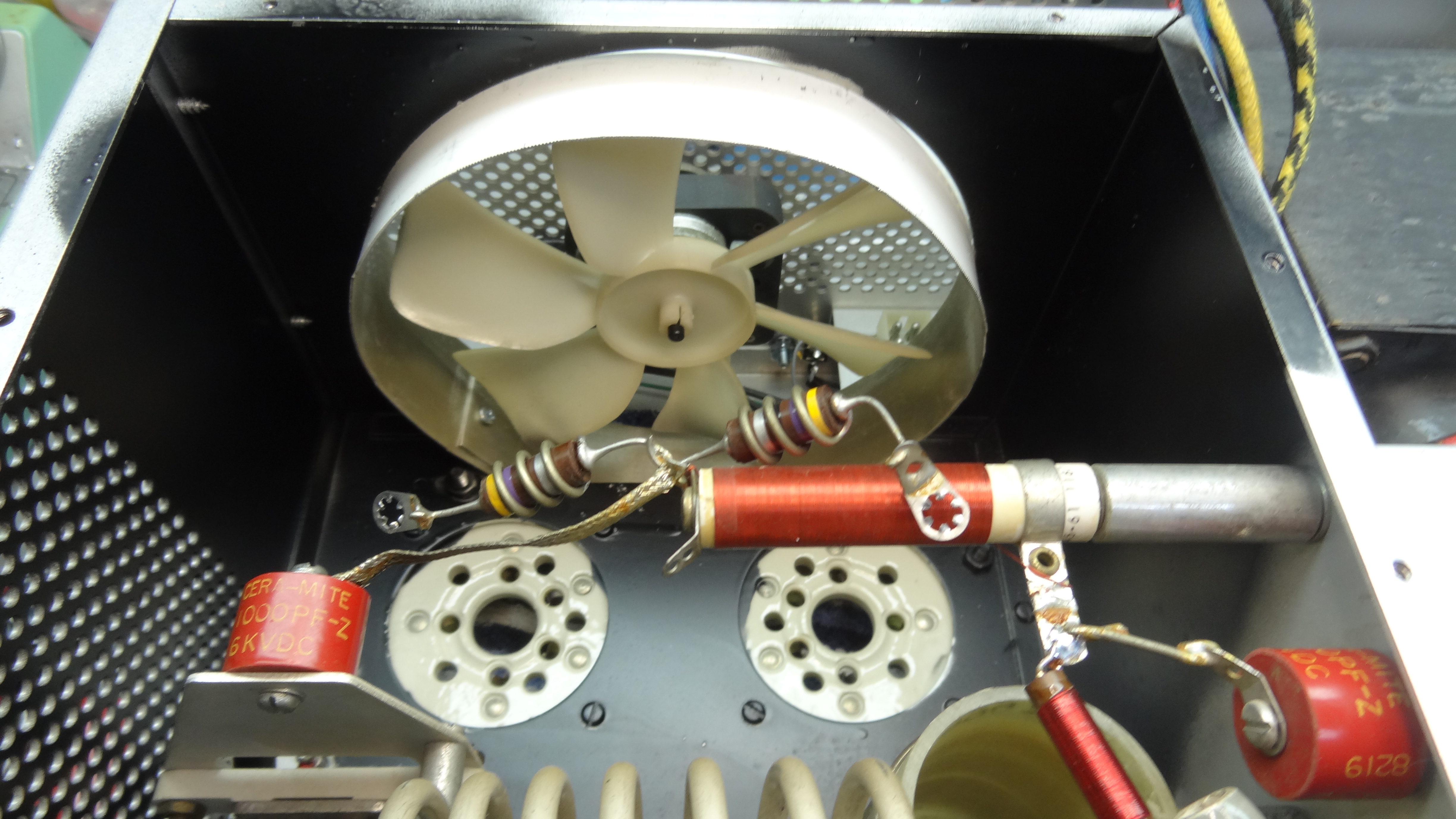 Finally two more mods were done. Painting the inside of the RF area around the tubes and adding a shroud
to focus the fan air on the tubes. Both help to reduce heat and extend tube life.
Finally two more mods were done. Painting the inside of the RF area around the tubes and adding a shroud
to focus the fan air on the tubes. Both help to reduce heat and extend tube life.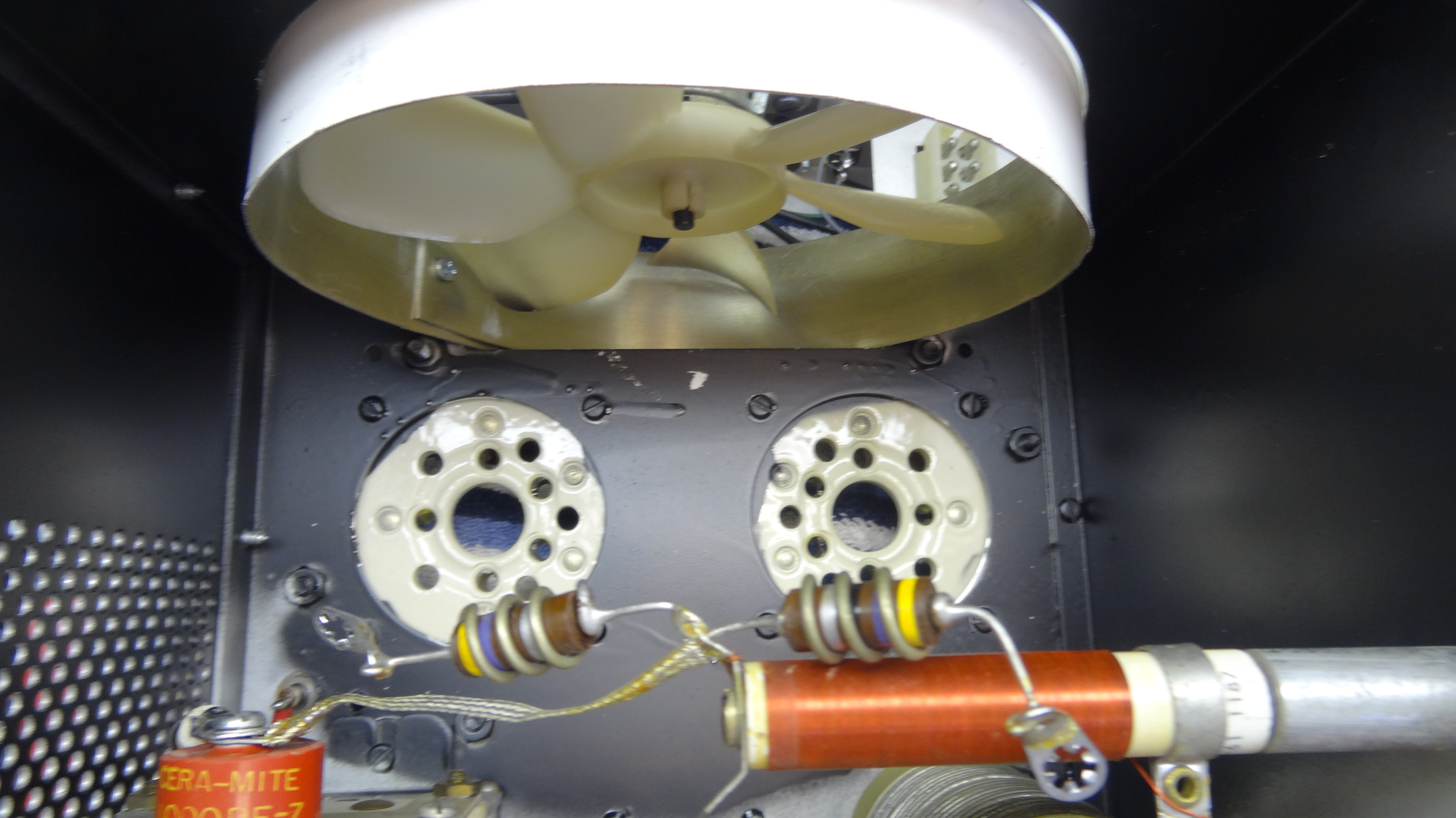 The shroud is made out of left over white aluminum flashing formed in a circle around a 4" PVC plumbing fitting. It
was secured with one screw at the overlap and formed a tight fit on the fan opening and was secured with silicone around the edge.
The shroud is made out of left over white aluminum flashing formed in a circle around a 4" PVC plumbing fitting. It
was secured with one screw at the overlap and formed a tight fit on the fan opening and was secured with silicone around the edge.After completion of the restoration testing began. The high voltage connector was reconnected and a variac was used to slowly bring the voltage up. I used two meters one directly connected to the high voltage and the other through a high voltage probe. I wanted to test the accuracy of the probe. In doing this DO NOT raise the voltage higher than the directly connected meter can withstand. I stopped at around 500V. As can be seen in the photo they matched with reasonable tolerance. Then lower the voltage to zero, remove the directly connected meter and you can proceed with bringing up the voltage slowly with the variac. I would do this in the tune mode. You should get 2400-2500 volts. Then switch to the SSB position and you should get close to 3000 volts. If all is well again lower the voltage to zero and wait for things to fully discharge and remove the high voltage probe. You can now proceed with RF tests.
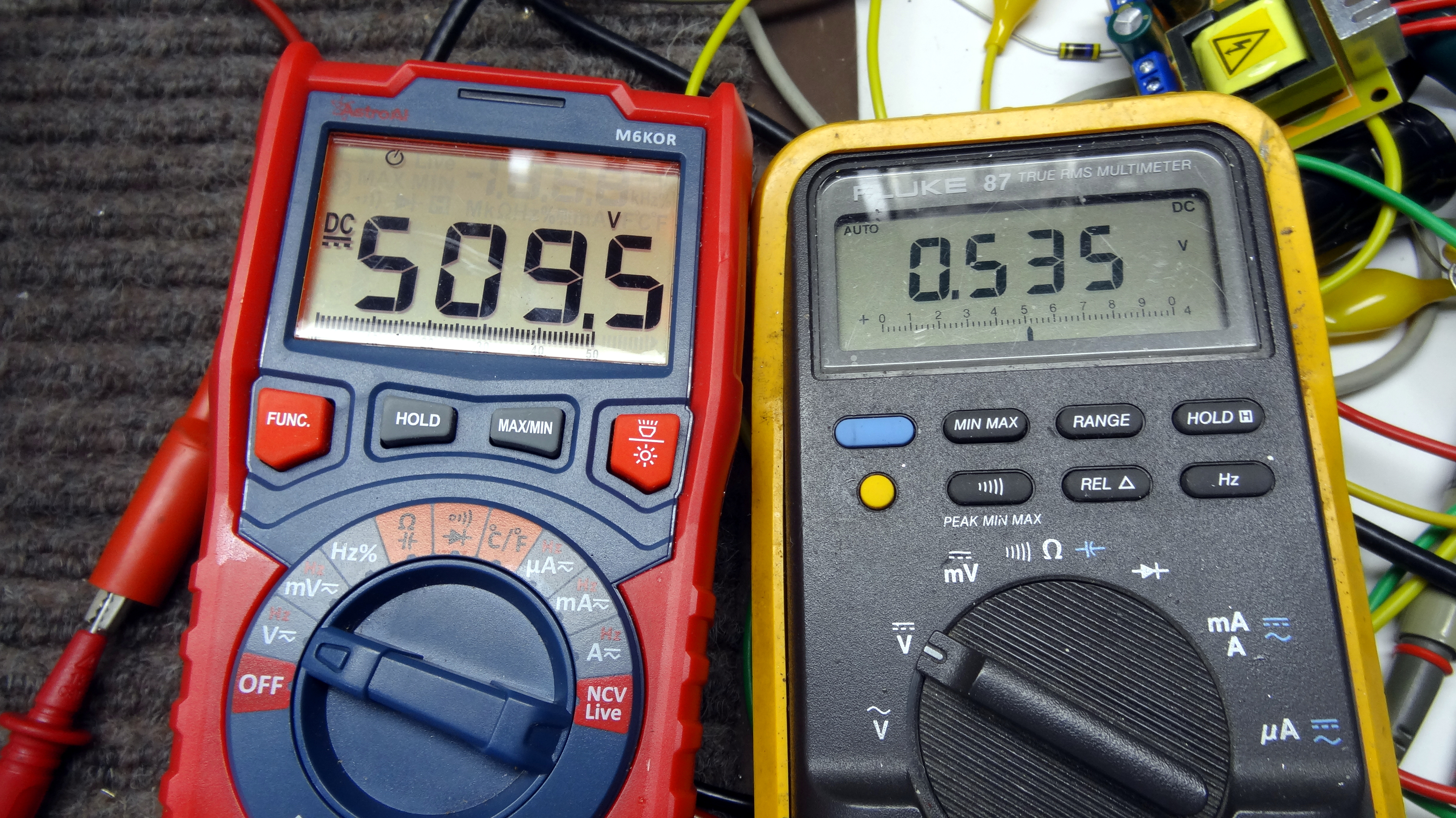 The left meter is directly connected and the right is through a HV probe. I trust the left meter so the
probe is reading a little high.
The left meter is directly connected and the right is through a HV probe. I trust the left meter so the
probe is reading a little high.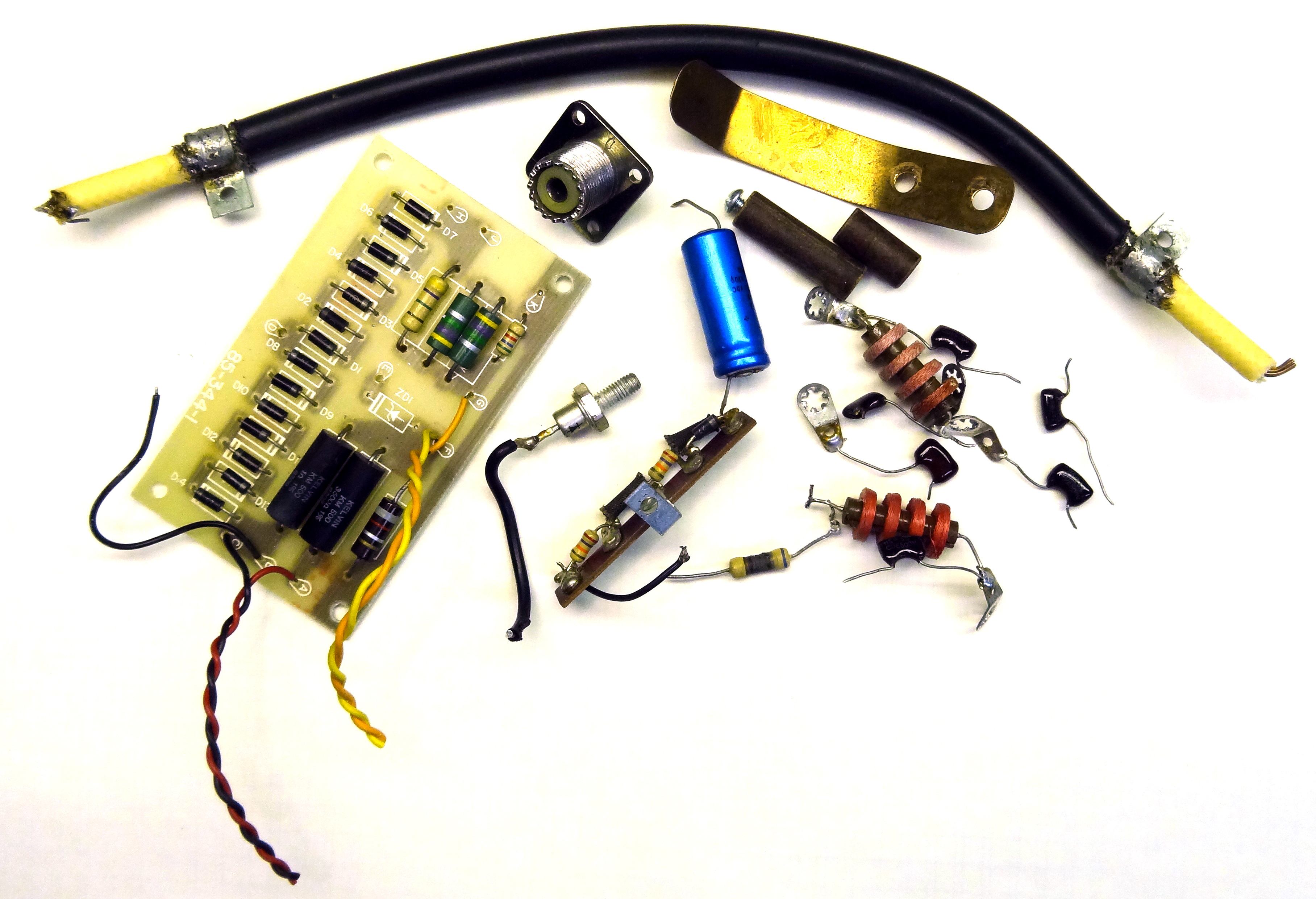 Don't you hate it when you take something apart and end up with extra parts! Old parts removed in restoration.
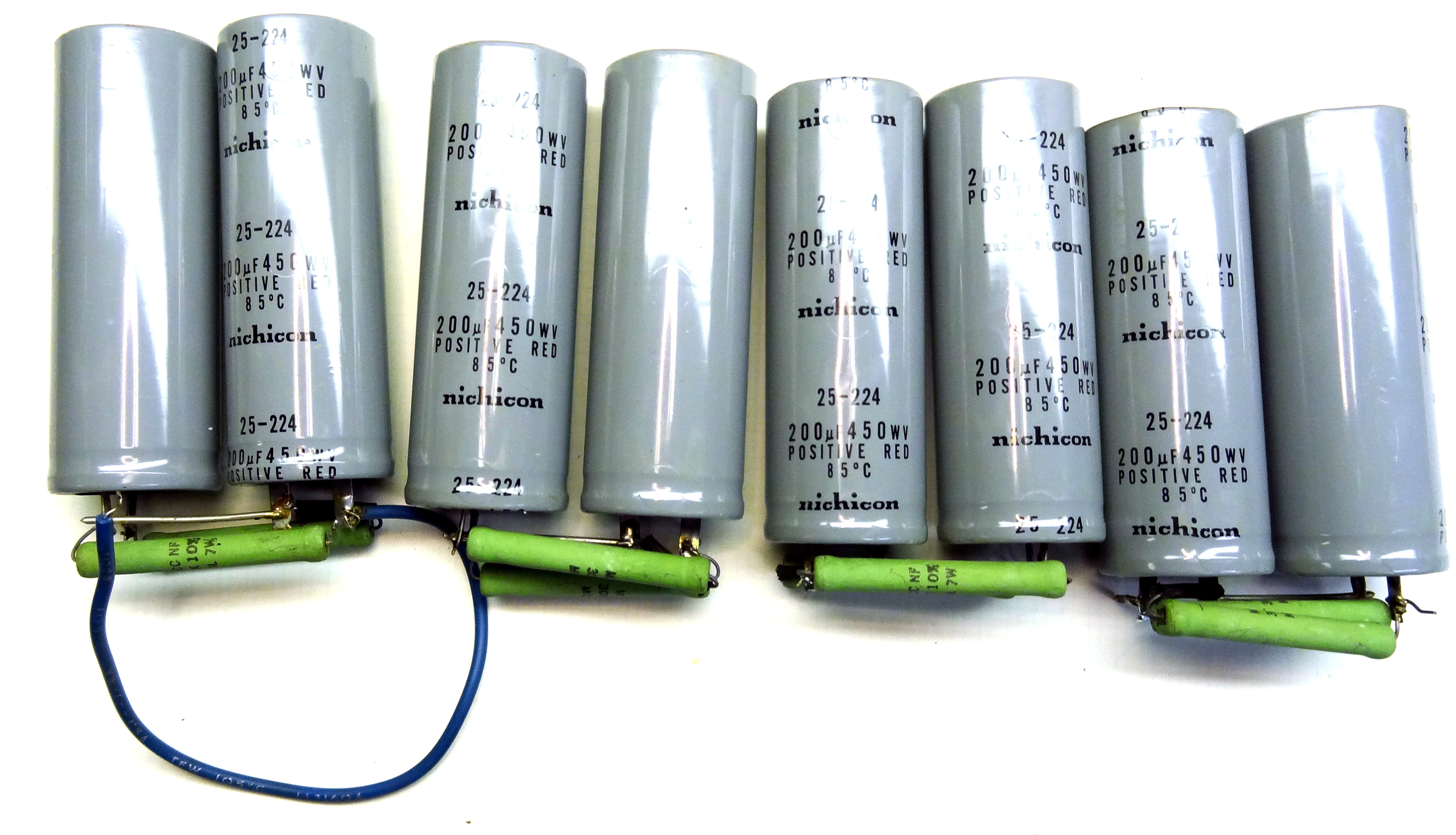 And the old capacitor bank and bleeders.
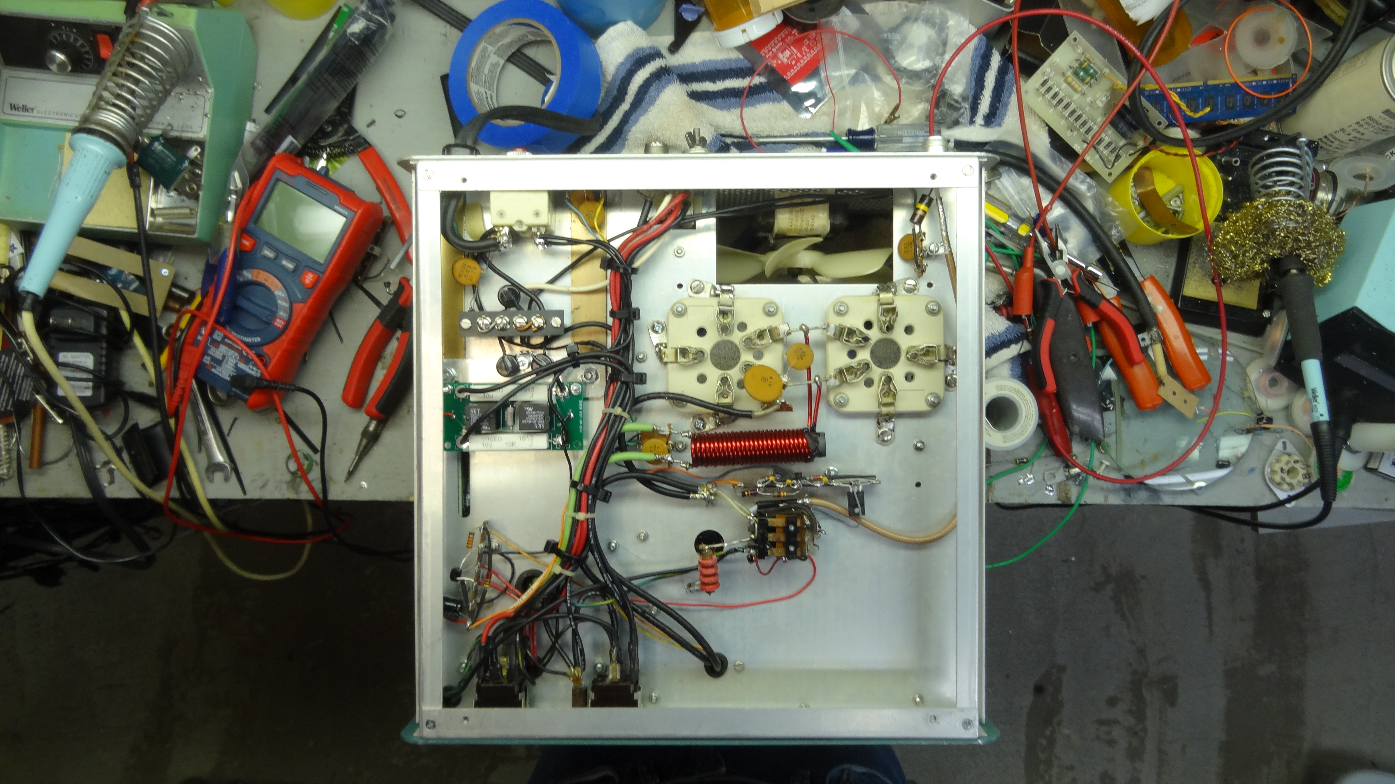 Time to clean up that messy bench!
CB Power Output Mentality
Tubes are expensive and harder and harder to get so why push your amplifier? I often see bragging about how much power a user can squeze out of a particular amplifier. The SB220 is capable of a full 1500 watts PEP but why push it. I call it the CB mentality and in reality it actually made more sense, although not legal, in the CB world where 5 watts was the legal limit. A 50 watt amplifier would achieve 10dB of signal improvement and that would be noticeable. When running higher power levels the expense you have to pay for 10dB or even 3dB is much higher. An amplifier running 1000 watts would need to double power to 2000 watts to achieve just a 3dB increase at the receive end. That 1000 watts of additional power to achieve 3dB. In the 5 watt CB case they would only have had to add 5 watts to achieve a 3dB gain. So at higher power levels it becomes increasingly more complicated and taxing on equipment to achieve minimal gains. Think of a 500KW short wave station, they would have to add another 500KW just to achieve 3dB of gain, a minimal amount.
So in reality running your SB220 at anything more than 1000 watts is a waste of energy and tube life. The difference between 1000 watts and 1500 watts is abut 1.75dB and not even noticeable at the receive end. This is why running this amplifier on 120V, limiting drive power, and maybe even running it in the tune position are recommended for long life of the tubes and components. In this SB220 I found that running it on 120V in the SSB position I could achieve close to 1000 watts with 40 watts of drive allowing my TS-590 to loaf and still have a significant signal.
SB220 Modifications
The Internet is full of SB220 modifications. Some are dubious at best. I picked out ones that made sense and were not contradicted by others. I highly recommend the Harbach kits. If you have an original unit you really need to replace the capacitor bank and the meter/bias/HV rectifier board is also recommended. If you are going to use it with a modern rig you must either fabricate your own soft-key circuit or buy the Harbach board. The original keying circuit in the SB220 (and SB200) is high voltage and will blow up any modern rigs keying circuit. The soft-start is optional. There is talk that the design of the SB220's filament transformer limits current surge at start up but it certainly would not hurt to add it.
Links for this Project
- Harbach Electronics SB220/221
- 3-500Z tubes What to look for
- Complete SB220 Assembly Manual with Schematic
- SB220 Schematic
This page last updated 10/31/2021
© 2021 - WA3DSP