Hammarlund SP600 Restoration
Hammarlund Radio History (from Wikipedia)
The Hammarlund Manufacturing Company was founded by Oscar Hammarlund in New York City, New York, United States in 1910. When the company was dissolved in 1973, it was among the USA's very oldest producers of radio equipment. The first Hammarlund plant was a loft operation engaged in radio component manufacturing on Fulton Street in lower Manhattan, New York City. Their variable capacitor designs quickly became industry standards, and the component's schematic symbol was adopted as the company's logo. In the mid-1920s, Hammarlund formed a partnership called Hammarlund-Roberts Co. specifically to offer kits for AM broadcast radios using Hammarlund parts. The company opened its major manufacturing facility in Mars Hill, North Carolina in 1951
In 1947 the SP-600 Super-Pro receiver, which surpassed the SP-200 in performance, was introduced, covering the frequency range of 540 kHz to 54 MHz with a 0-100 calibrated mechanical band spread. The SP-600 series were widely used throughout the world for military, laboratory and commercial application
While Hammarlund was most famous for its amateur/short-wave receiver lines such as the Super Pro series and the HQ series (which includes the HQ-100, 110, 120, 129, 145, 150, 160, 170, 180, 200 and 215), a number of transmitters were also produced. These saw only limited use.
Hammarlund also built a substantial quantity of the VHF FM "Village Radios" for the United States Agency for International Development (AID) to use in Vietnam, as well as a number of land-mobile radios and transceivers for the Citizens band radio market
Even as the company continued to produce communications equipment for the amateur, commercial, and Citizens Band radio markets, it underwent frequent changes of ownership. The first was in the late 1950s when Hammarlund was sold to Telechrome. Several years later Telechrome sold out to Giannini Scientific. In the late 60's the company was once again sold to the Electronic Assistance Corporation (EAC). But, this sale was final. The product line was sold off in parts or phased out. The Cardwell Condenser Corporation purchased all remaining stocks, and in 1973 the Hammarlund factory closed. At the time of its dissolution, Hammarlund was among the USA's very oldest producers of radio equipment.
Today, many Hammarlund radios are collected, restored and used by vintage amateur radio enthusiasts.
Hammarlund SP-600 Restoration Project
(Click any photo to see a larger view)
I have had my Hammarlund SP-600 for many years sitting in a rack and never turned on. After recently (12-2021) restoring it I am sorry I did not do it earlier. It is a very nice receiver. I also lucked out as I undoubtedly have a later model with disc ceramic capacitors and not the troublesome "bumble bee" capacitors that the early models had. I did replace several capacitors, mostly the oil filled bathtub type and electrolytic capacitors. None that I replaced were actually bad as tested upon removal. My reason for replacing was usually for a smaller size or in the case of the oil filled caps to avoid future physical leakage.
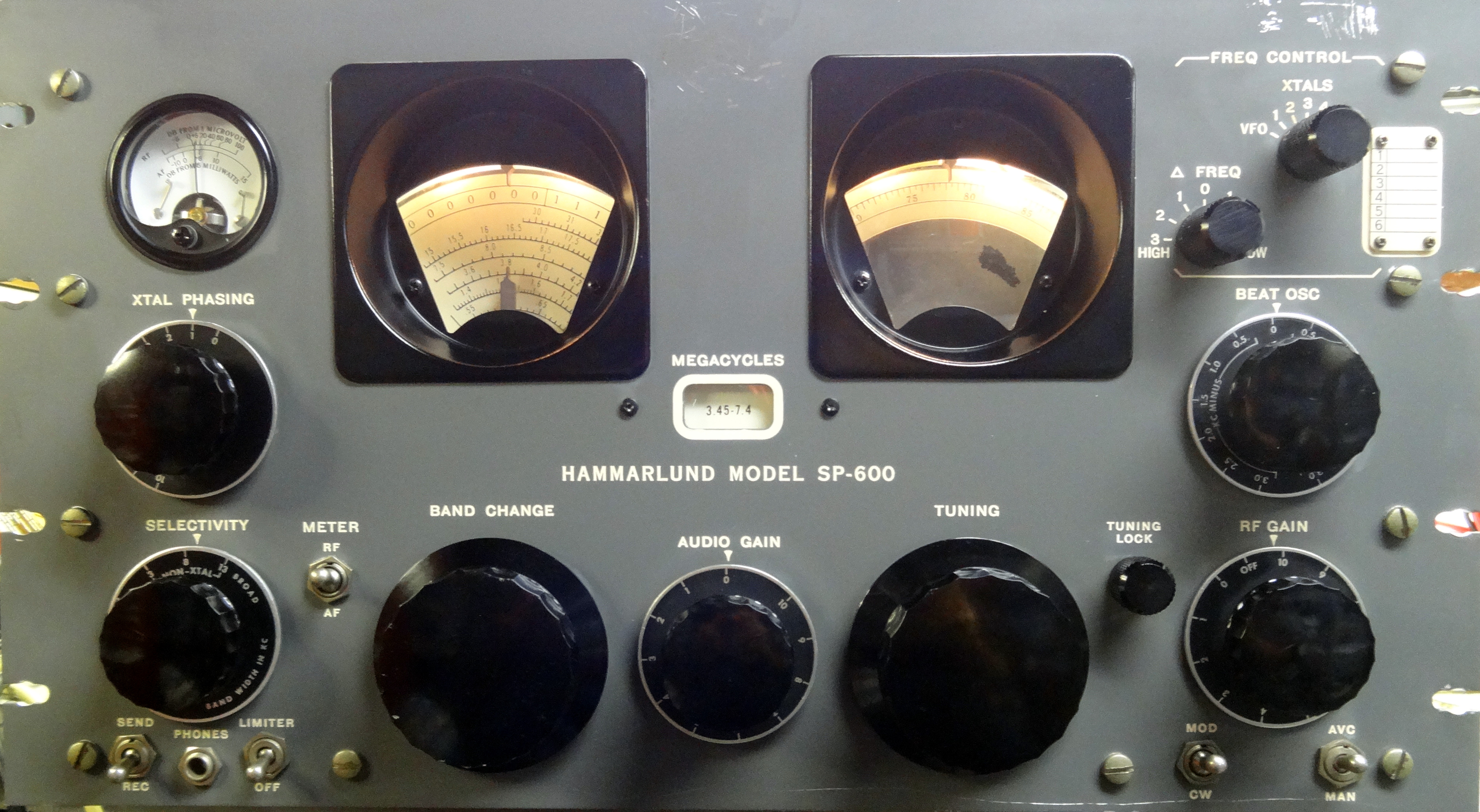
Since this SP-600 had no markings or serial number visible anywhere it is hard to place in among the various models of the SP-600. The opening photo on this page is the actual front panel of my SP-600. It had a stock 2 wire lamp cord style power cord and plug which I replaced with a three wire cord and grounded plug. My first project was the removal and replacement of all of the bathtub style capacitors. Doing this makes it much easier to reach components as the replacements are a fraction of the original size.
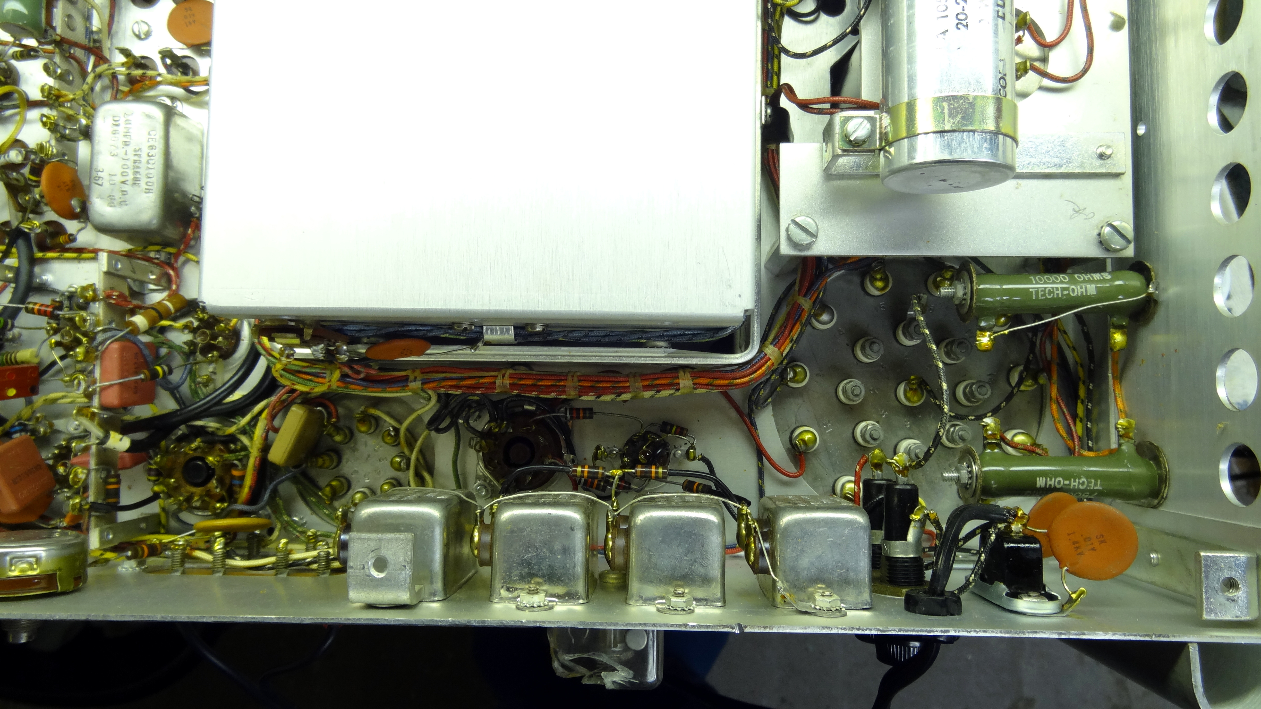 This is a view of the under chassis before starting the restoration. As you can see it was very clean. The five visible bathtub capacitors were replaced as well as the triple electrolytic filter capacitor at the upper right.
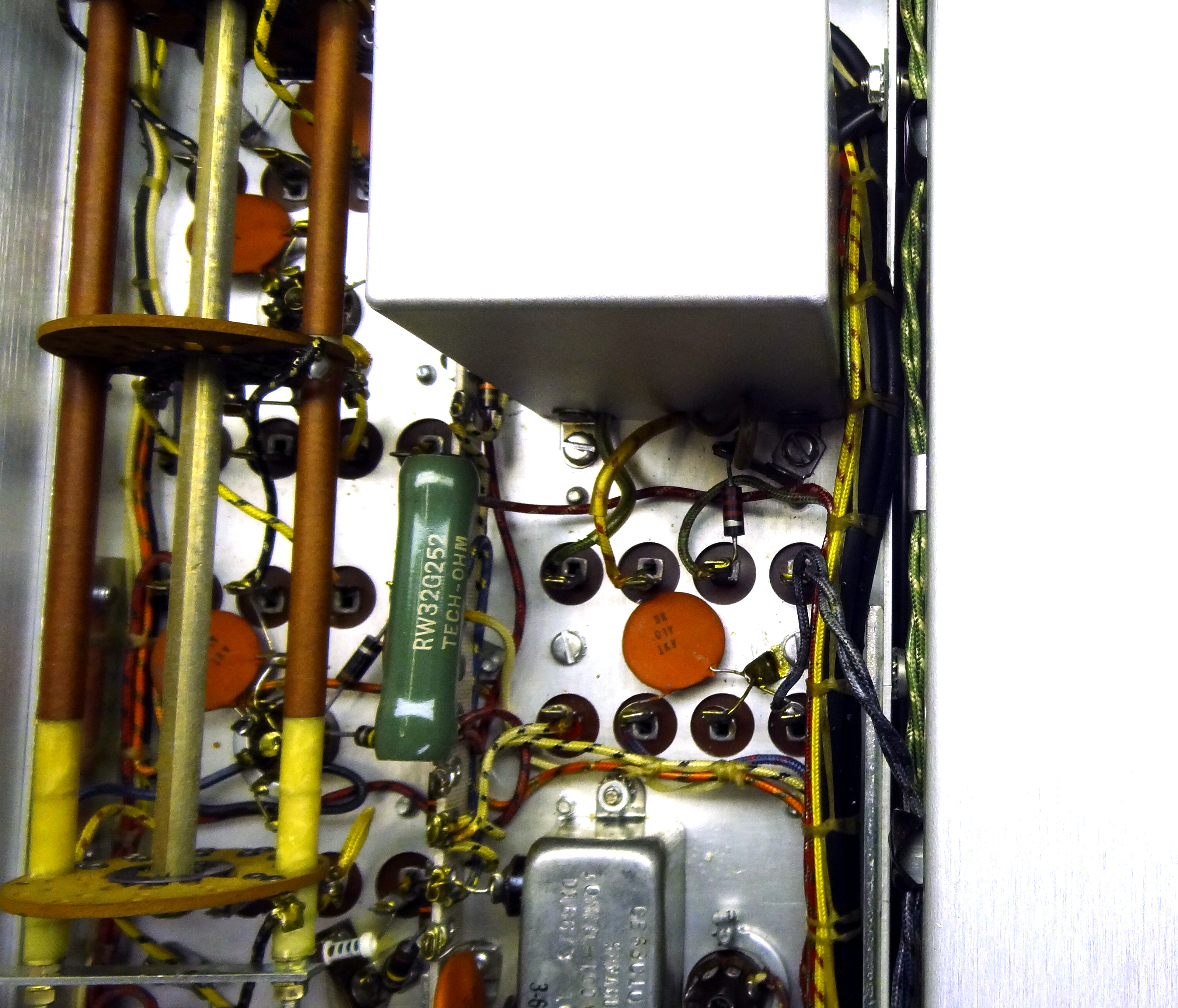 Another view of the under chassis prior to restoratoin.
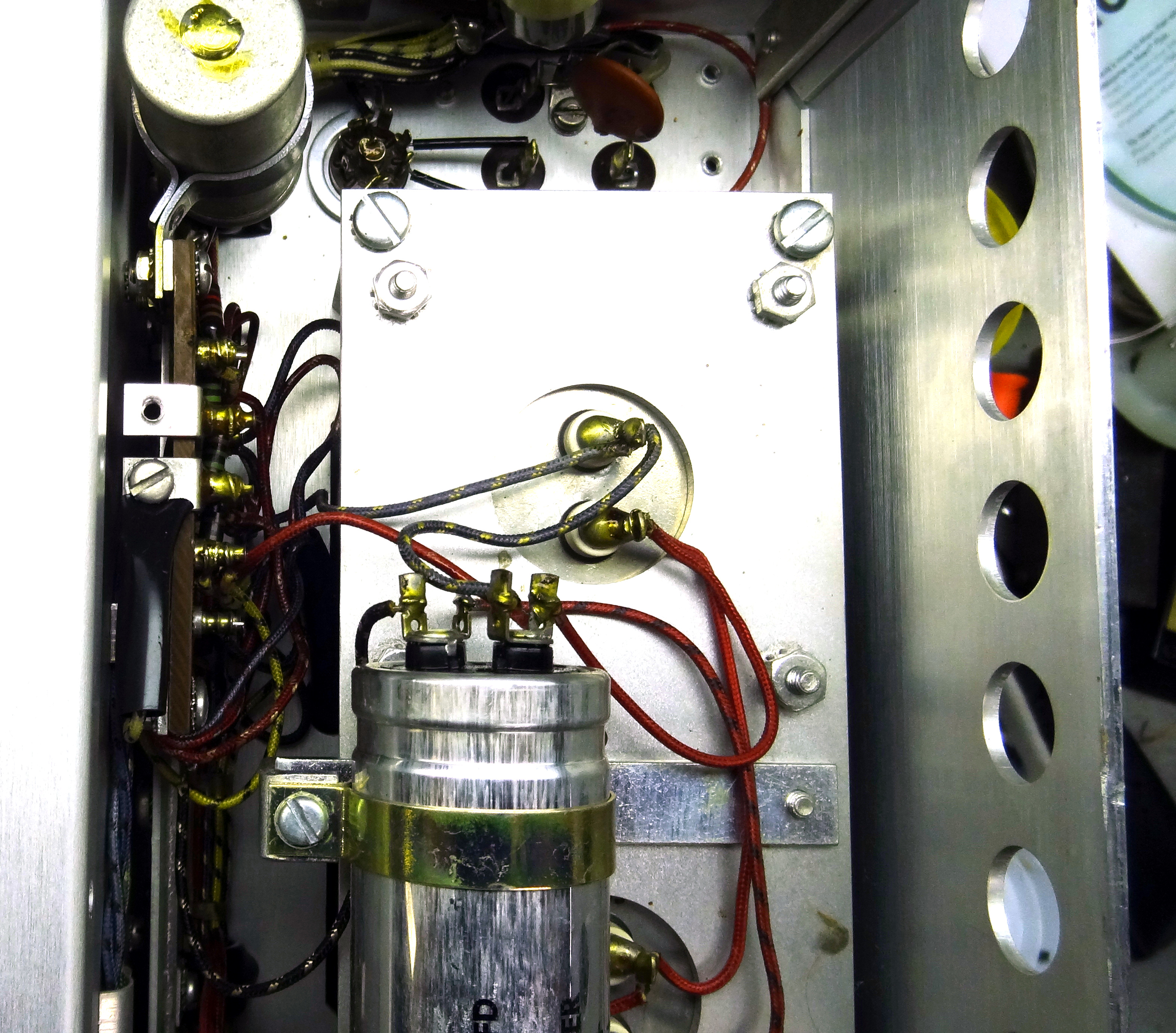 Showing original electrolytic capacitor mounting
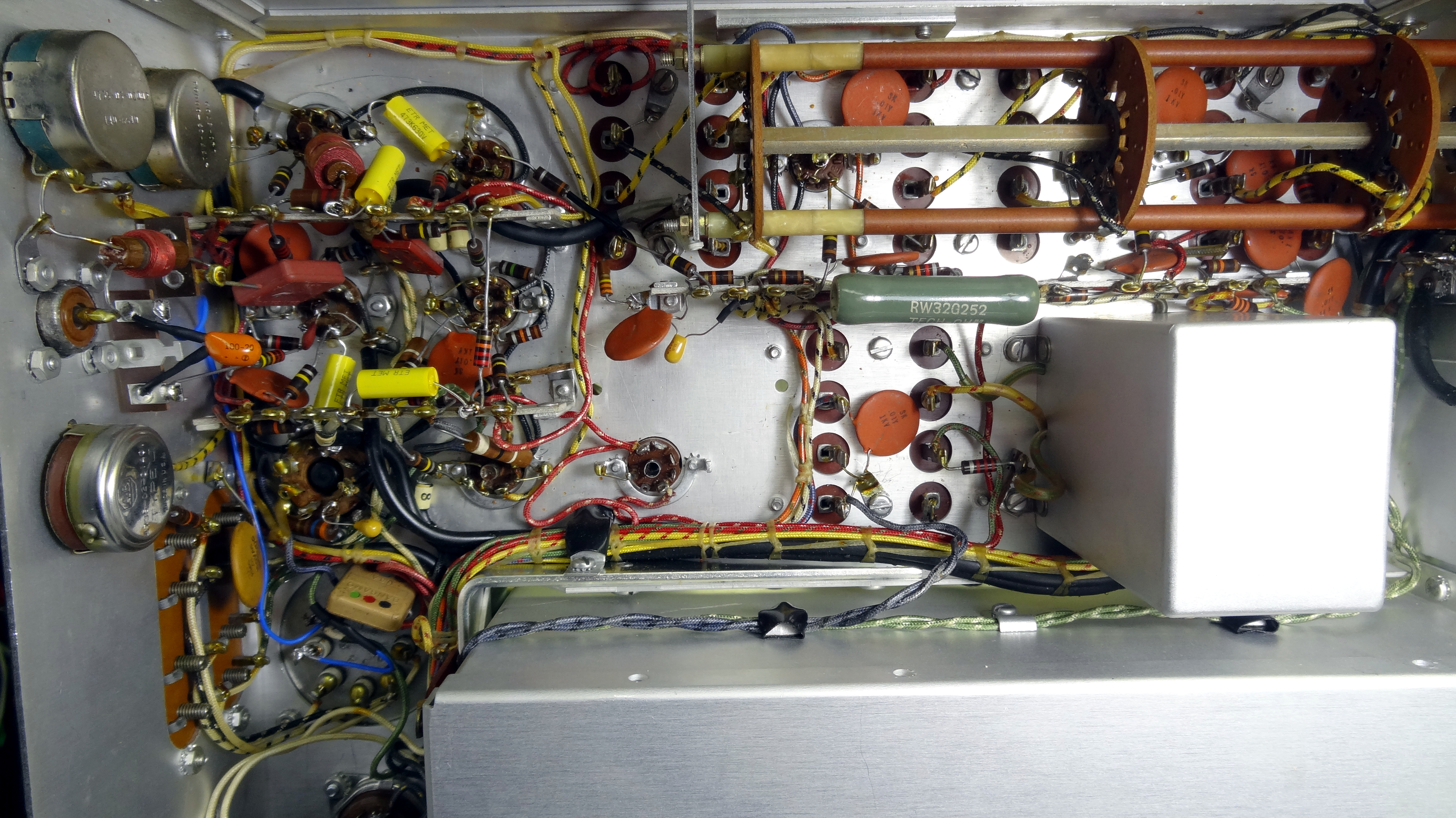 Replacement capacitors (yellow) in one section of under chassis.
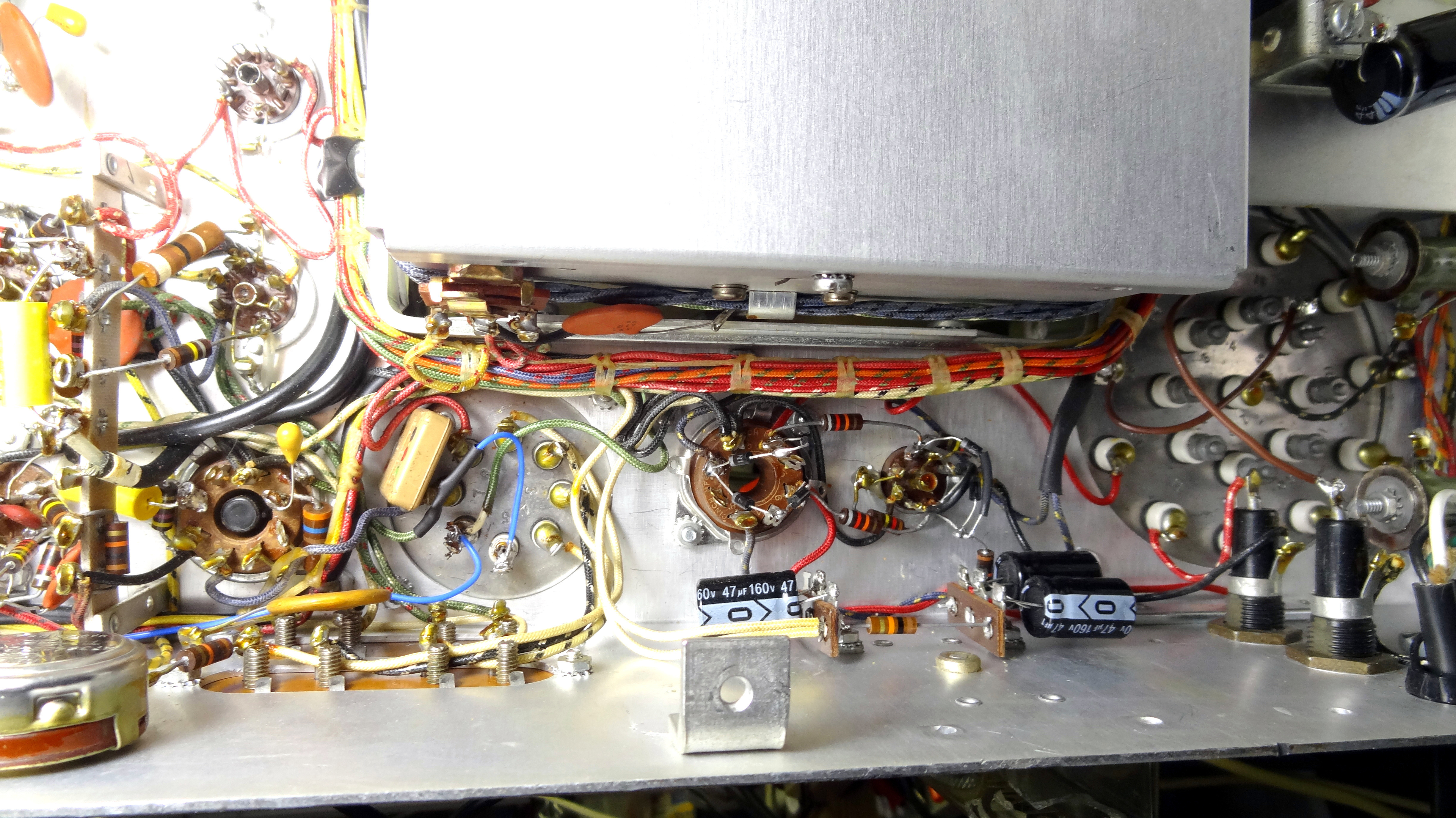 Showing replacement of bias bathtubs and solid-state B+ and bias supplies.
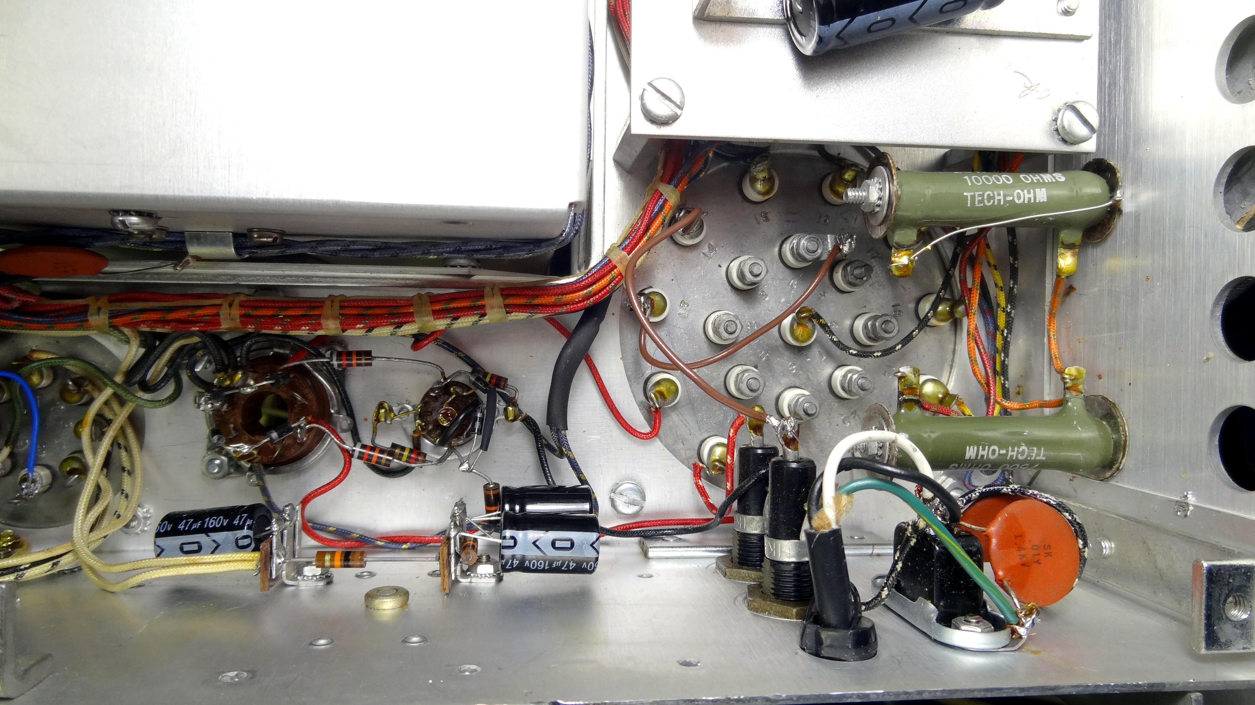 View showing solid-state mods and power transformer wiring (see text).
The SP-600 offers a great deal of voltage selection taps on the power transformer primary. The default is the 117 volt tap which would produce almost exactly 6.3VAC filament voltage if it was selected and that primary voltage was supplied. If you don't want to solid-state the supplies and your line voltage is in that area then you might decide to not solid-state. I am a big advocate of solid-stating the supplies for a number of reasons. It eliminates about 15 watts of wasted power and heat and it also frees up a 5V winding to use as a boost or buck of the primary. Since the SP-600 has taps at 95, 108, 117, 130, and higher voltages using a buck or boost of 5 volts on these ranges gives you quite a bit of leeway.
The radio is spec'ed at a nominal 117VAC input and typically that tap is the one selected. Hammarlund used a 5R4 rectifier tube and it is unclear why they used this type, as it is typically used at higher voltages. I suspect it was for reliability as this radio was designed to run 24/7/365! The 5R4 has a wider filament to plate spacing to accommodate higher voltages, but this also leads to a higher voltage loss in the tube, typically 40 volts or more. When installing a solid-state replacement for the 5R4 this loss does not exist and thus the B+ is increased significantly. Fortunately, the stock SP-600 has a capacitive input power supply with two chokes. This allows the removal of the first capacitor and the increasing of the second and third capacitor values, thus making it a choke input power supply. This is the preferred power supply design as it has better regulation and is much easier on the replacement diodes, there is no need for any additional series resistance. This also lowers the B+ back down to a very reasonable value and actually slightly less than the design voltage, which is a good thing. Because my line voltage is very steady at about 121V, I used the now unused 5V winding to buck the primary. This gave me almost exactly 6.3VAC for the filaments, another design goal. Removing these two tubes reduced the power consumption by about 15 watts and reduces the chassis heat considerably. The B+ runs around 240-250VDC. Here are the steps for the solid-state mod.
- Remove V19, 5R4
- Remove V20, 6AL5
- Remove wires (3) on pins 13 and 14 of power transformer
- Connect these three wires together
- Install diodes (1A 1000V) 2 in series from V19 pin 4 to pin 2
- Install diodes (1A 1000V) 2 in series from V19 Pin 6 to pin 2
In both case bands towards pin 2 - Remove wire from power transformer pin 4 (117 volt tap)
- Jumper pin 13 to pin 4
- Connect wire removed from pin 4 to pin 14
- Connect diode (1A 1000V) from V20 pin 1 to pin 2
- Connect diode (1A 1000V) from V20 pin 5 to pin 2
In both cases band AWAY from pin 2 - Remove C161A - At choke terminal closest to the front panel
- Replace C161B and C with 50uf @450V
- Replace C158, C159, C160 with 47uf @160V
Note - Capacitor values are increased from stock and I would suggest using these values or higher. These capacitors are a fraction of the physical size of the old stock lower values.
It was suggested to use a surge device to keep turn on B+ at a reasonable level until the tubes heated and full current was drawn. I found this to not be necessary as the choke input filter arrangement in combination with the instant on gas regulator tube instantly drawing critical current resulted in a very reasonable turn on voltage. The other issue with a current limiter is that they are often prone to failure and it is no fun taking this thing out of the rack for repair!
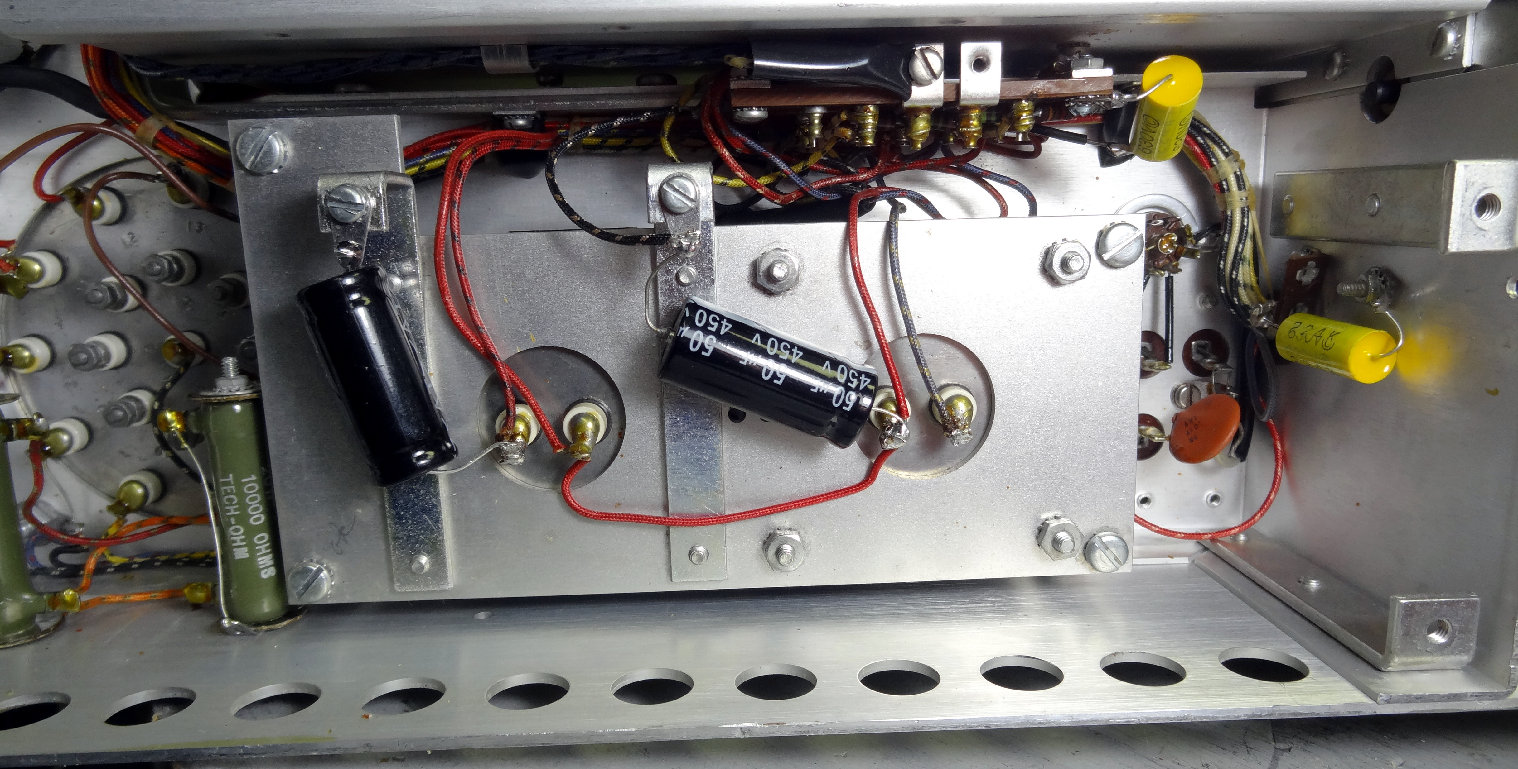 Electrolytic capacitors replaced. Note front (right most) choke has no capacitor making this a choke input power supply.
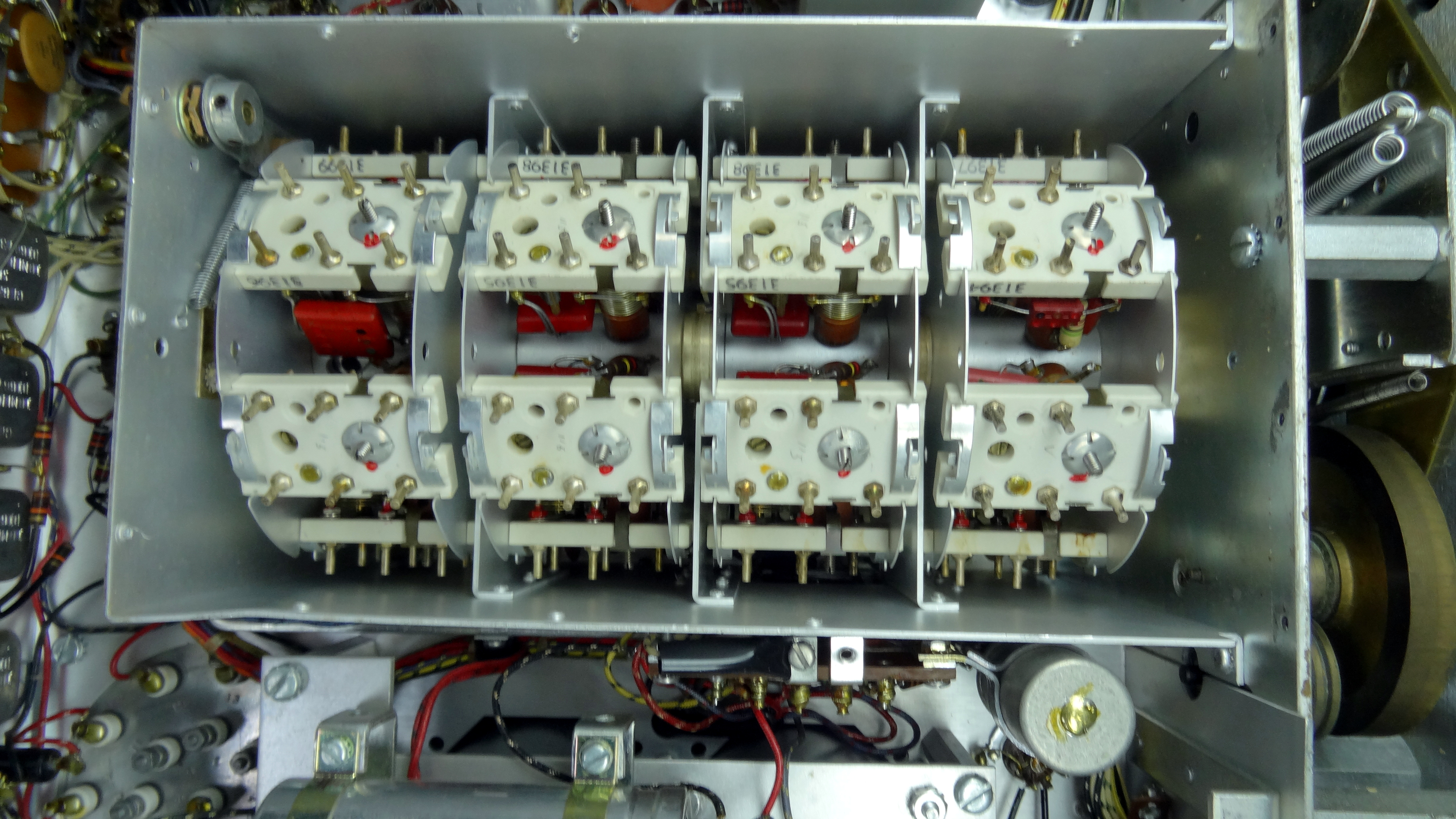 The RF section was very clean and in good shape and required no maintenance.
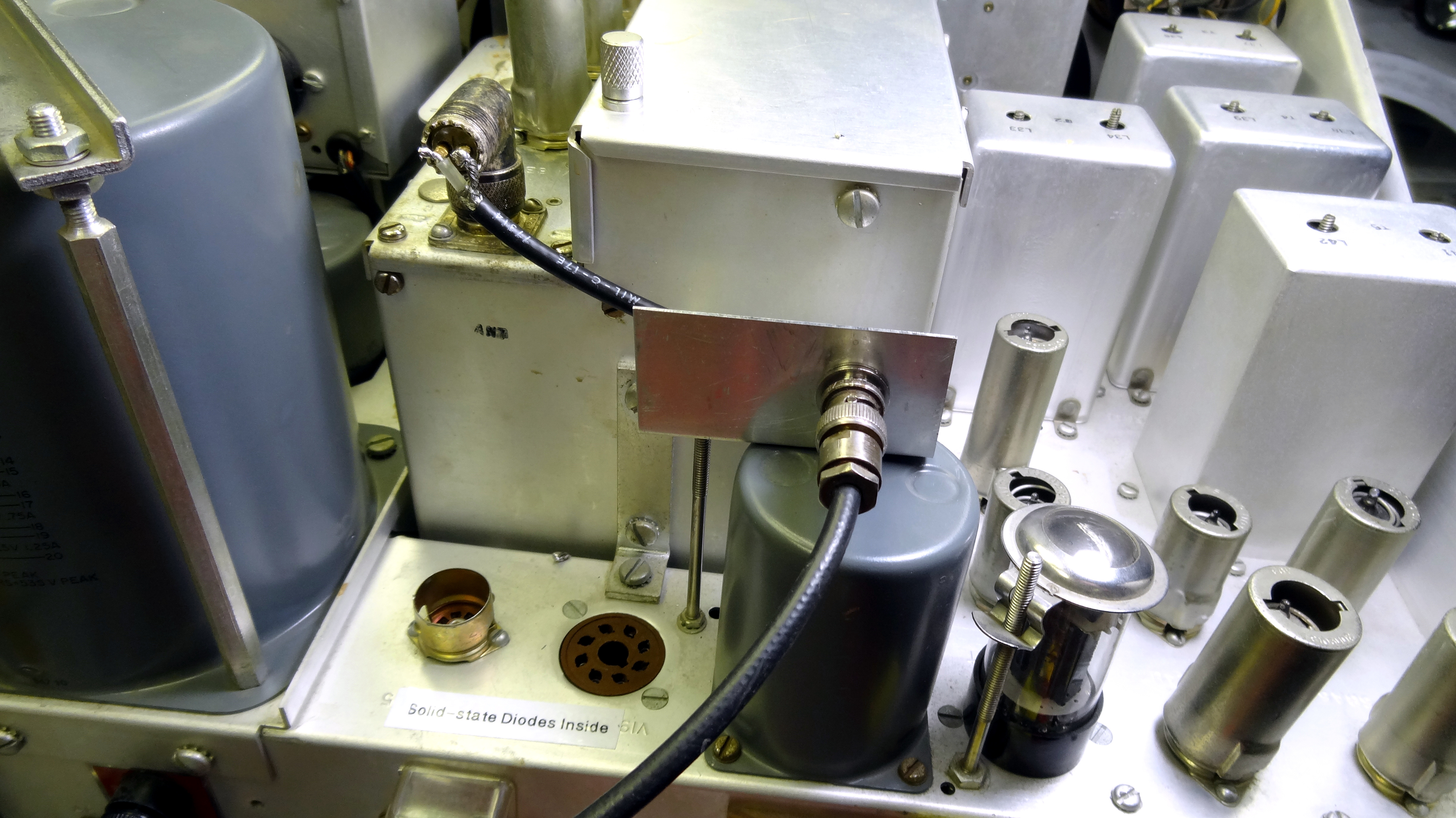 Rather than modify the original twinax antenna connection and adapter was made to a BNC mounted on the now unused 5R4 rectifier hold down screw.
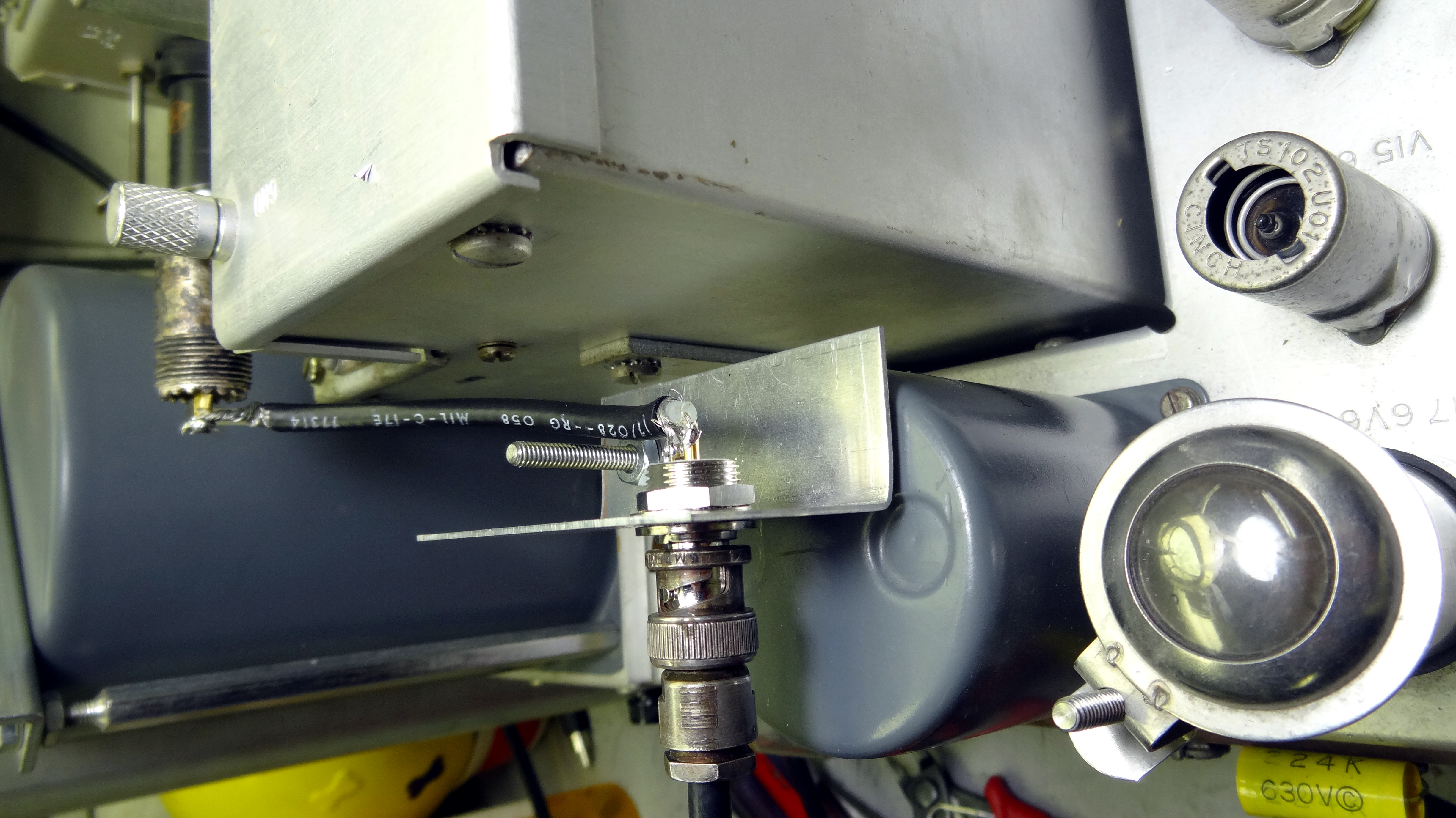 Pins were selected to snugly fit into the twinax connector and a short piece of RG58 cable connects to a chassis mount BNC. The BNC is ground isolated as I had one on my junk box but this is not necessary.
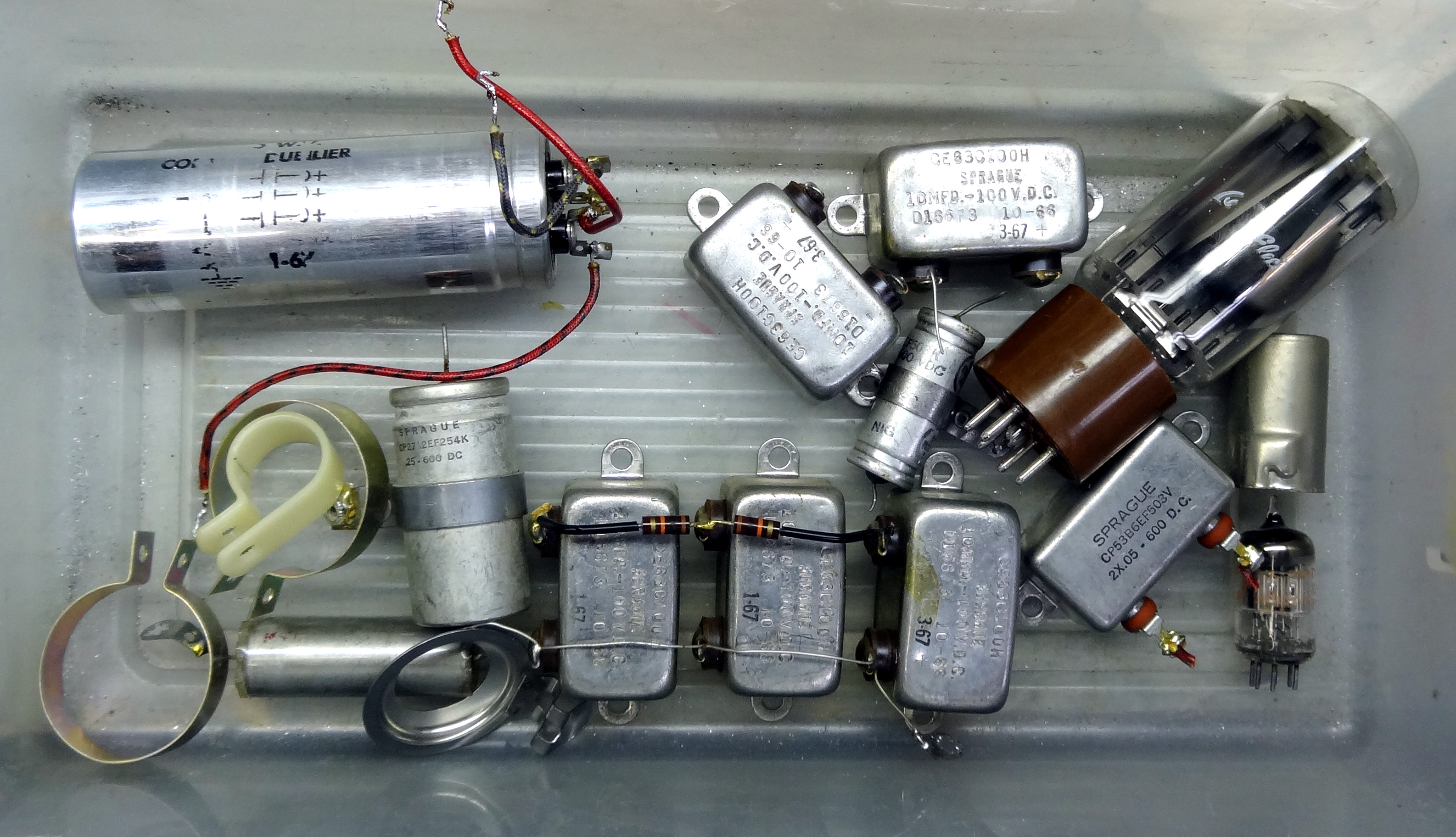 Parts removed and replaced in the restoration
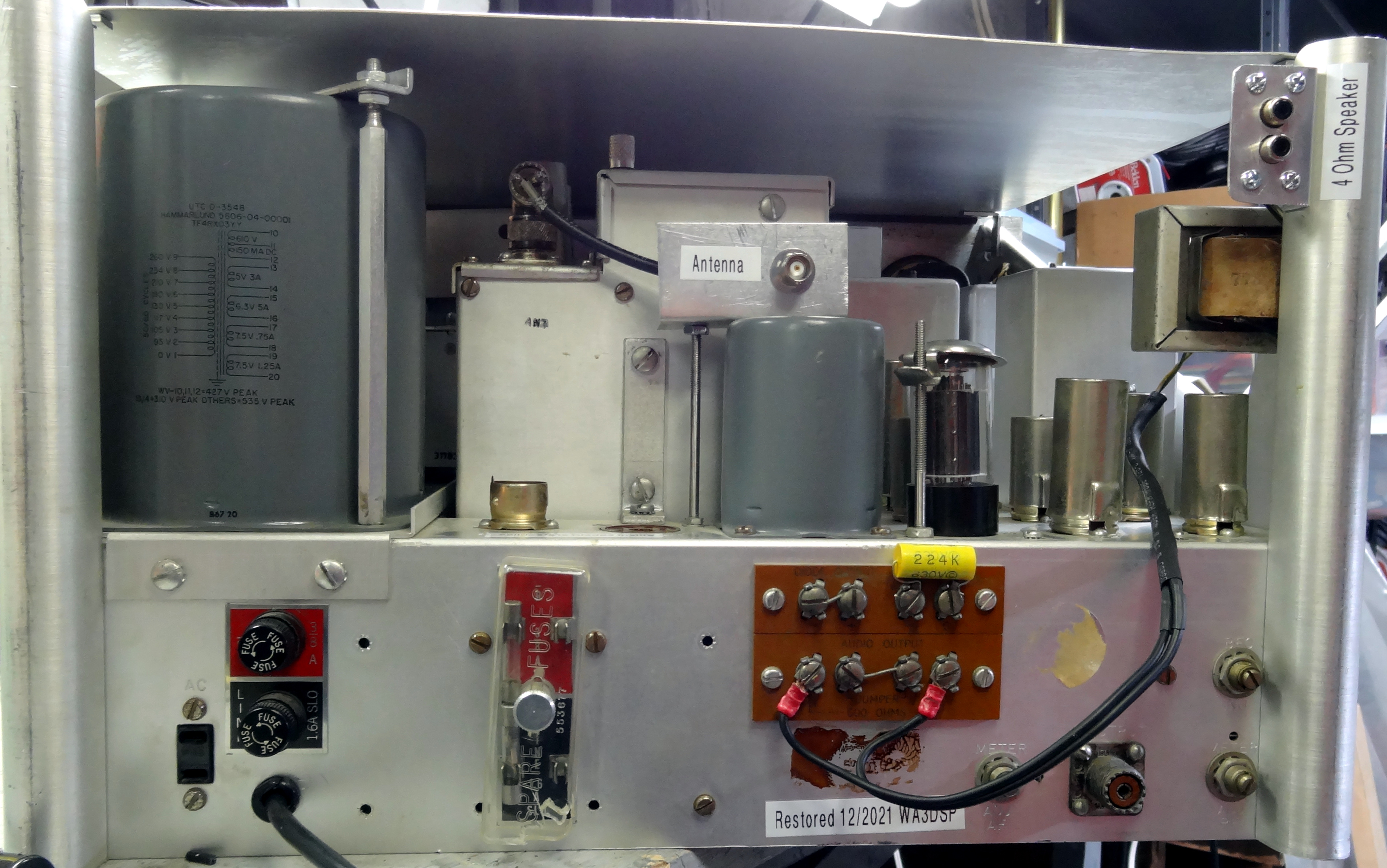 The completed restoration showing the rear panel. The SP-600 has a 600 ohm balanced audio output and the transformer to drive a low impedance speaker from the 600 ohms was typically mounted in the speaker cabinet. This is not useful when you have many receivers and a patching system to speakers that are all low impedance as I do. So the transformer was mounted on the right rear vertical rail and an RCA connector for the low impedance speaker is shown also mounted to the side rail with an aluminum bracket. Both connectors are in parallel.
Hammarlund Radio Links
- Wikipedia Hammarlund Radio
- Hammarlund Super Pro Wikipedia
- List of SP-600 designations
- Western Radio museum SP-600
- Original SP-600 manual
- Later SP-600 JX17 manual
- Various SP-600 manuals
This page last updated 12/31/2021
© 2021 - WA3DSP