Collins 32V-1 Restoration
Collins Radio History (from Wikipedia)
Arthur A. Collins founded Collins Radio Company in 1933 in Cedar Rapids, Iowa. It designed and produced both shortwave radio equipment and equipment for the burgeoning AM radio broadcast industry. Collins was solicited by the military, the scientific community, and the larger AM radio stations for special equipment. Collins supplied the equipment to establish a communications link with the South Pole expedition of Rear Admiral Richard E. Byrd in 1933.
In 1936, Collins had begun production of the 12H audio console, 12X portable field announcers box, and the 300E and 300F broadcast transmitters. Throughout World War II, the 212A1 and 212B1 replaced the 12H design. Collins became the principal supplier of radio and navigation equipment used in the military, where uncompromising performance was required.
In the postwar years, the Collins Radio Company expanded its work in all phases of the communications field, while broadening its technology. New developments such as flight-control instruments, radio-communication devices, and satellite voice transmissions created great opportunities in the marketplace. Collins Radio Company provided communications for the United States' role in the Space Race, including equipment for astronauts to communicate with earth stations and equipment to track and communicate with spacecraft. Collins communications equipment was used for Projects Mercury, Gemini and Apollo, providing voice communication for every American astronaut traveling through space. In 1973, the U.S. Skylab program used Collins equipment to provide communication from the astronauts to earth.
See https://en.wikipedia.org/wiki/Rockwell_Collins for more information on Collins.
Click on any photo for a larger view.
Welcome to my restoration and modification of the Collins 32V-1 Transmitter. I previously restored and modified the companion 75A-1 receiver http://www.crompton.com/hamradio/collins/75a1/ several years ago. I hope you enjoy this 32V-1 restoration and if you have any questions you can email me at my QRZ address - 73 Doug, WA3DSP.
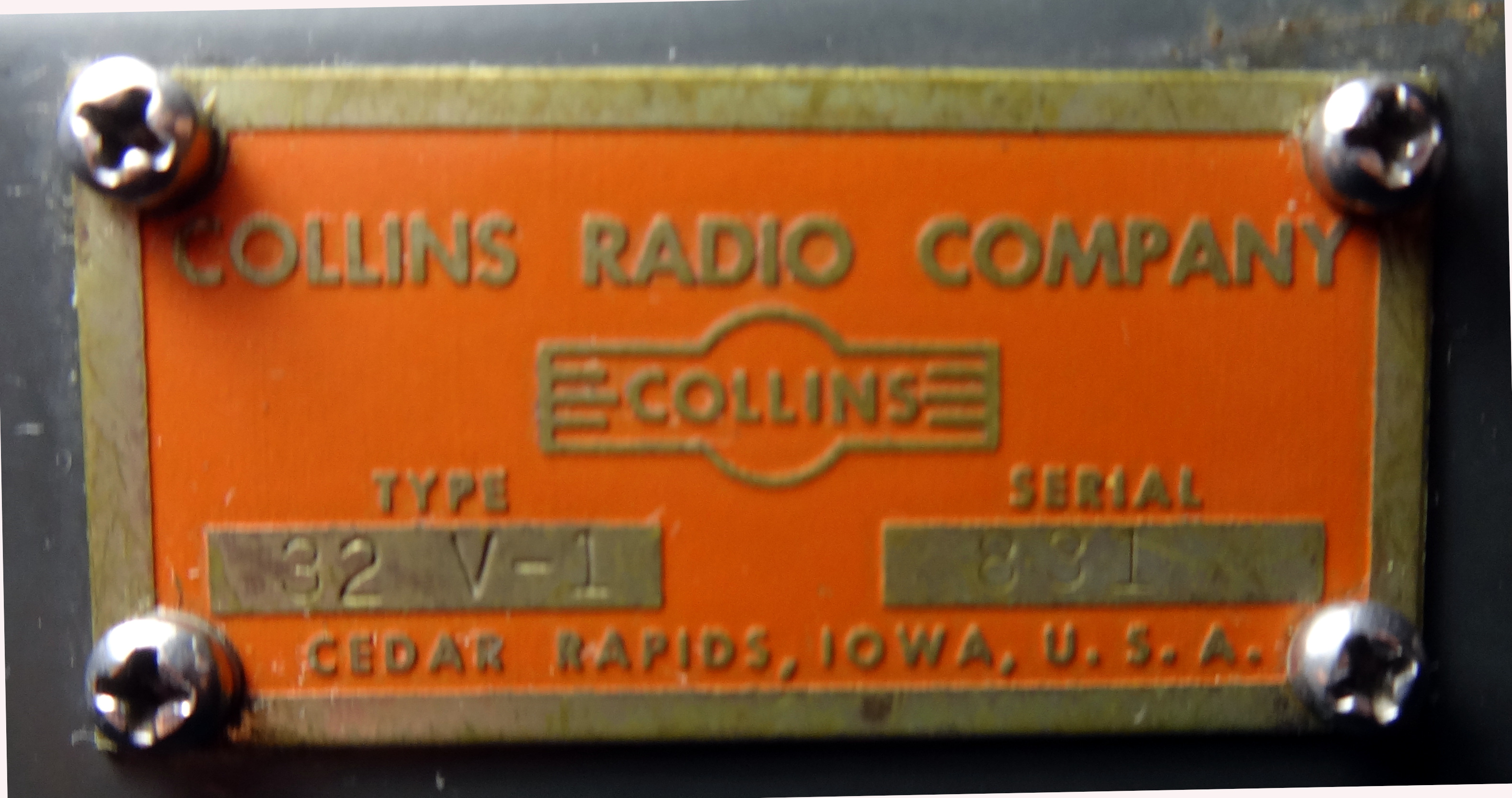 Serial 831. Part of the last batch of 753 manufactured in 1948.
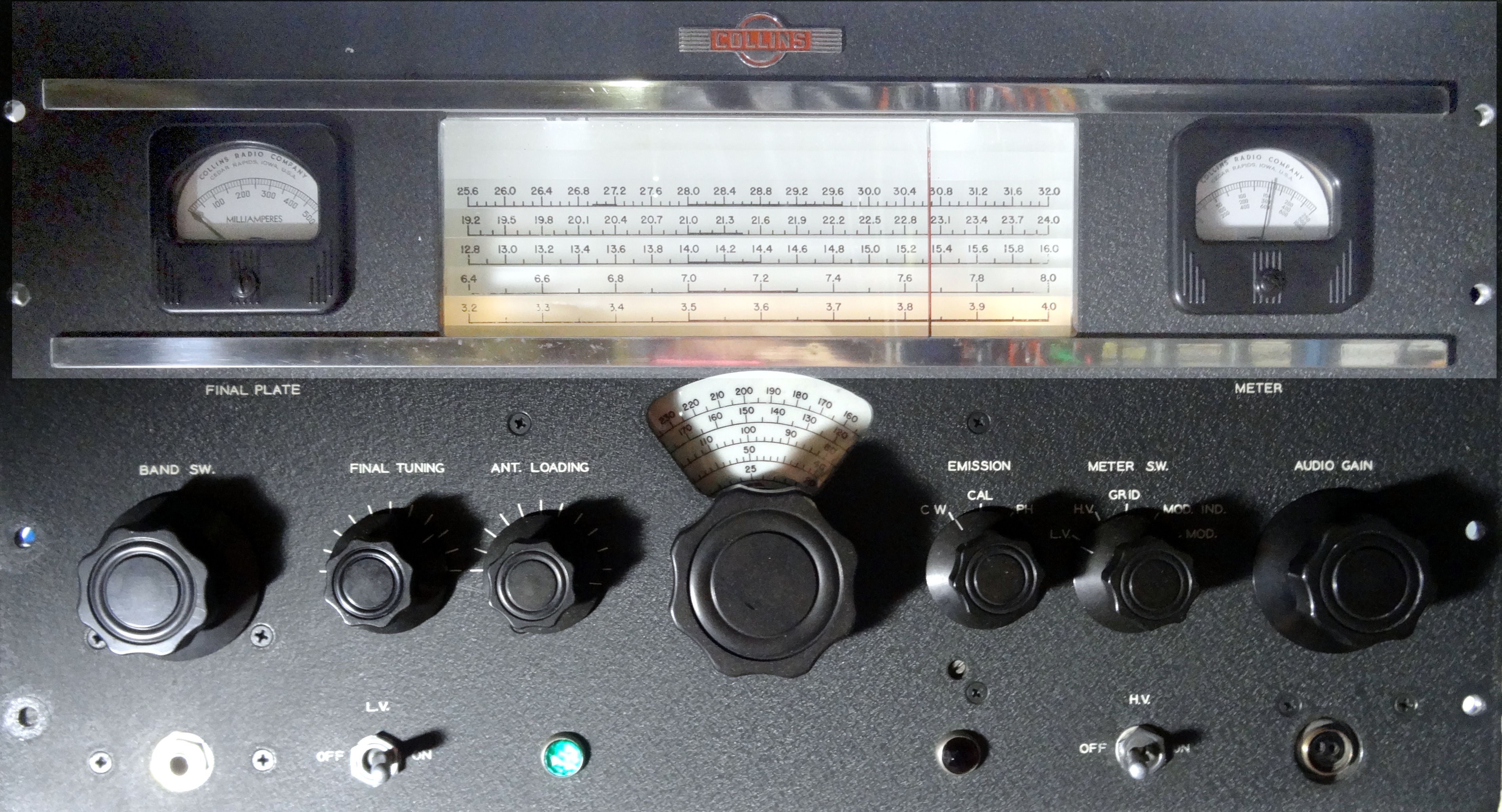
 I received the transmitter from Gary, K1IC in basically stock condition. One of the high voltage oil capacitors had broken down and leaked and he had partially started a replacement. The following photos show the condition of the transmitter on arrival. The front panel was in excellent condition and only needed mild cleaning. It appears in the opening photo. Please refer to the photos below and links at the end of this document for the details of all modifications.
 This view shows the HV Capacitor removed and setting next to the transmitter.
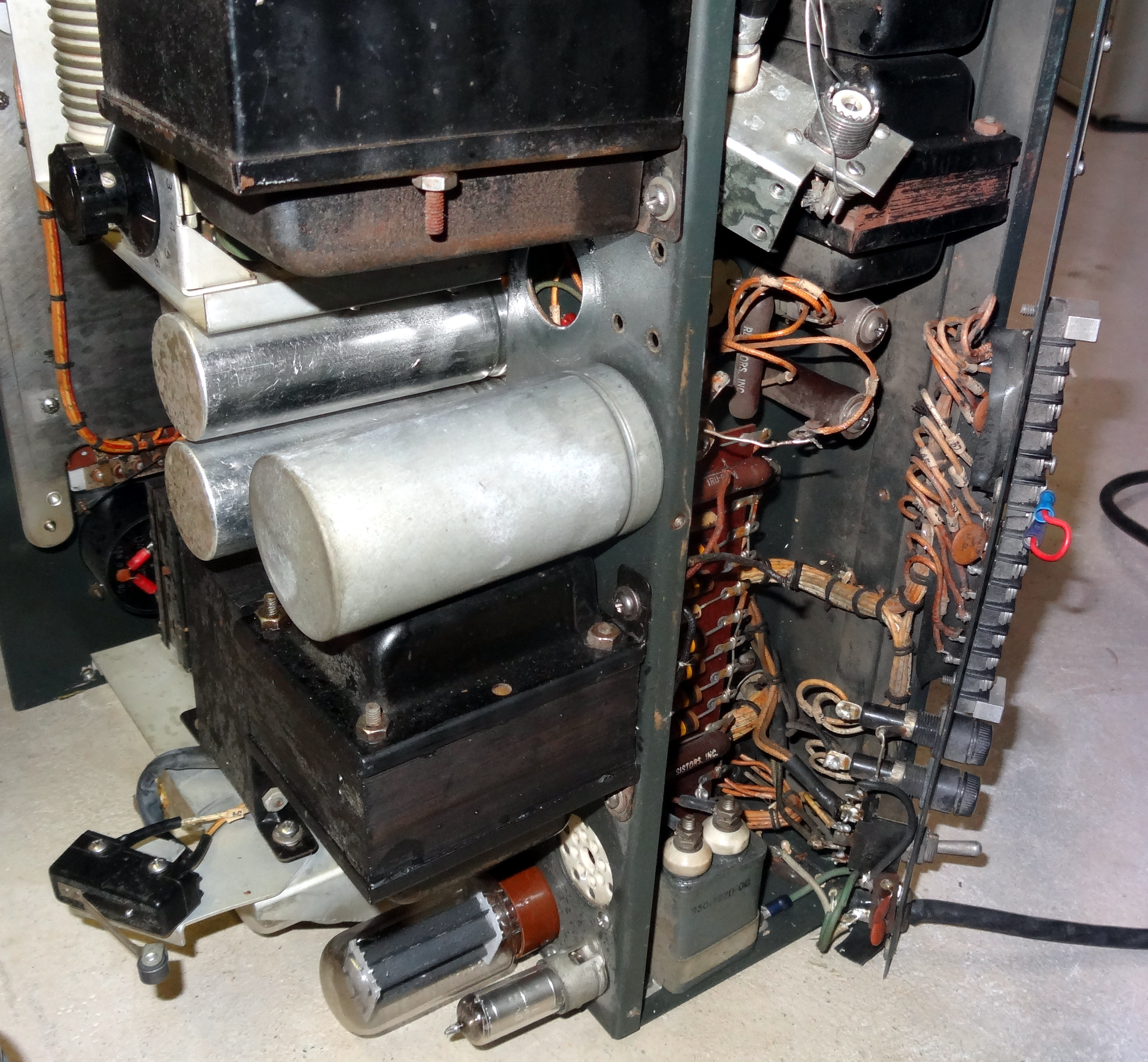 Showing opening where the capacitor was mounted.
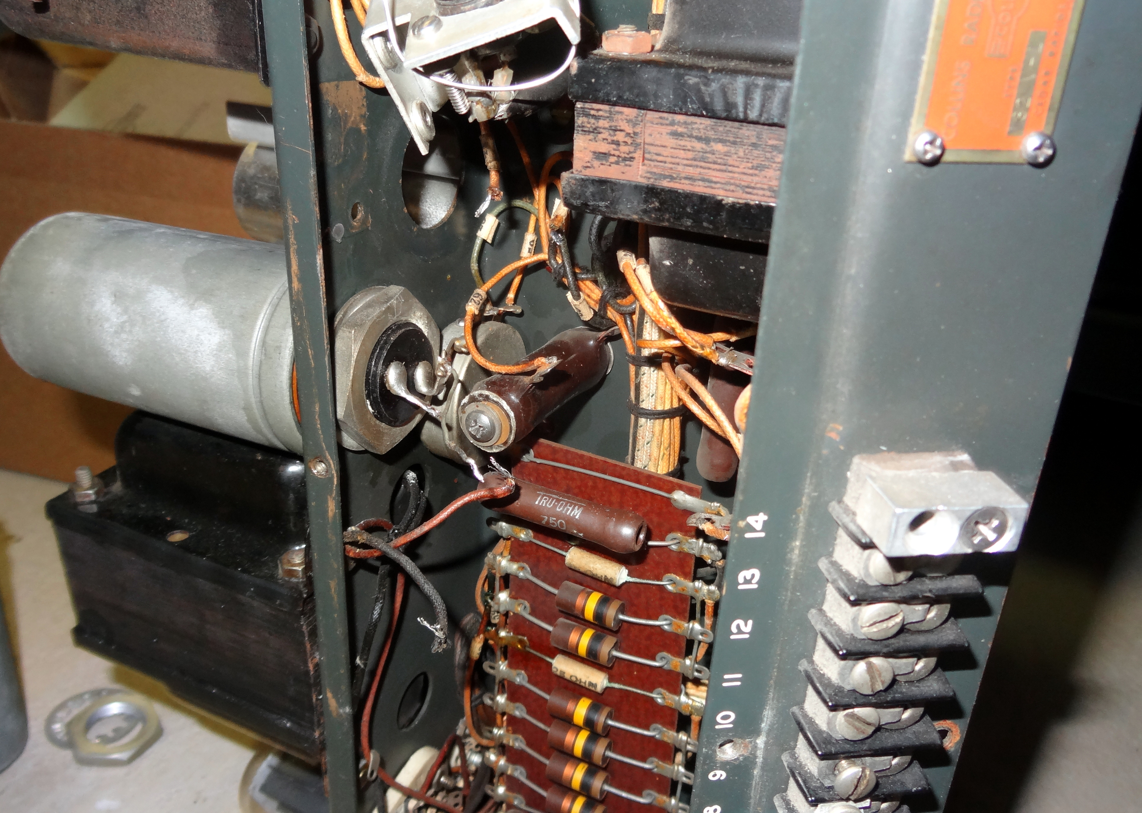 Bottom view of HV capacitor mounting.
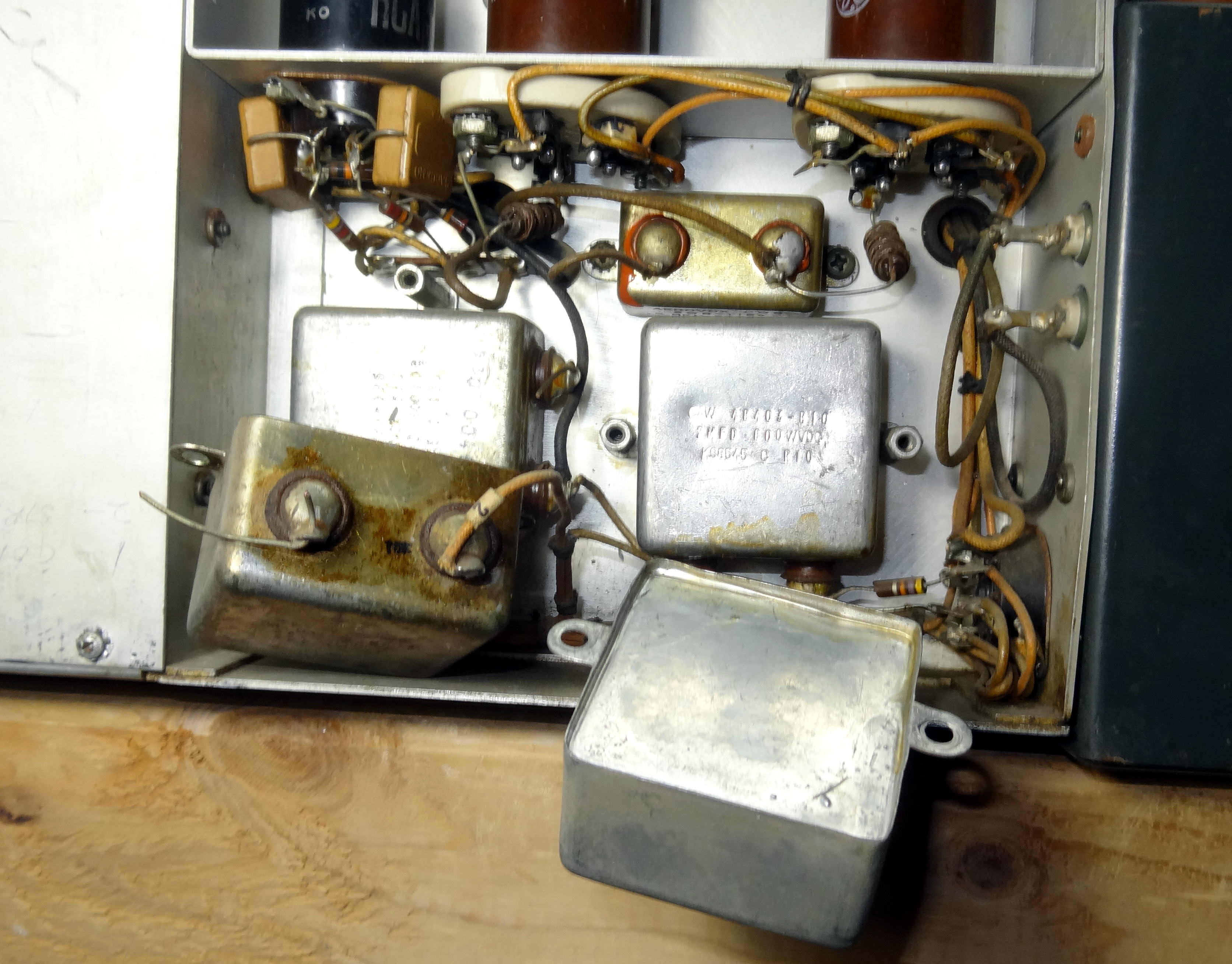
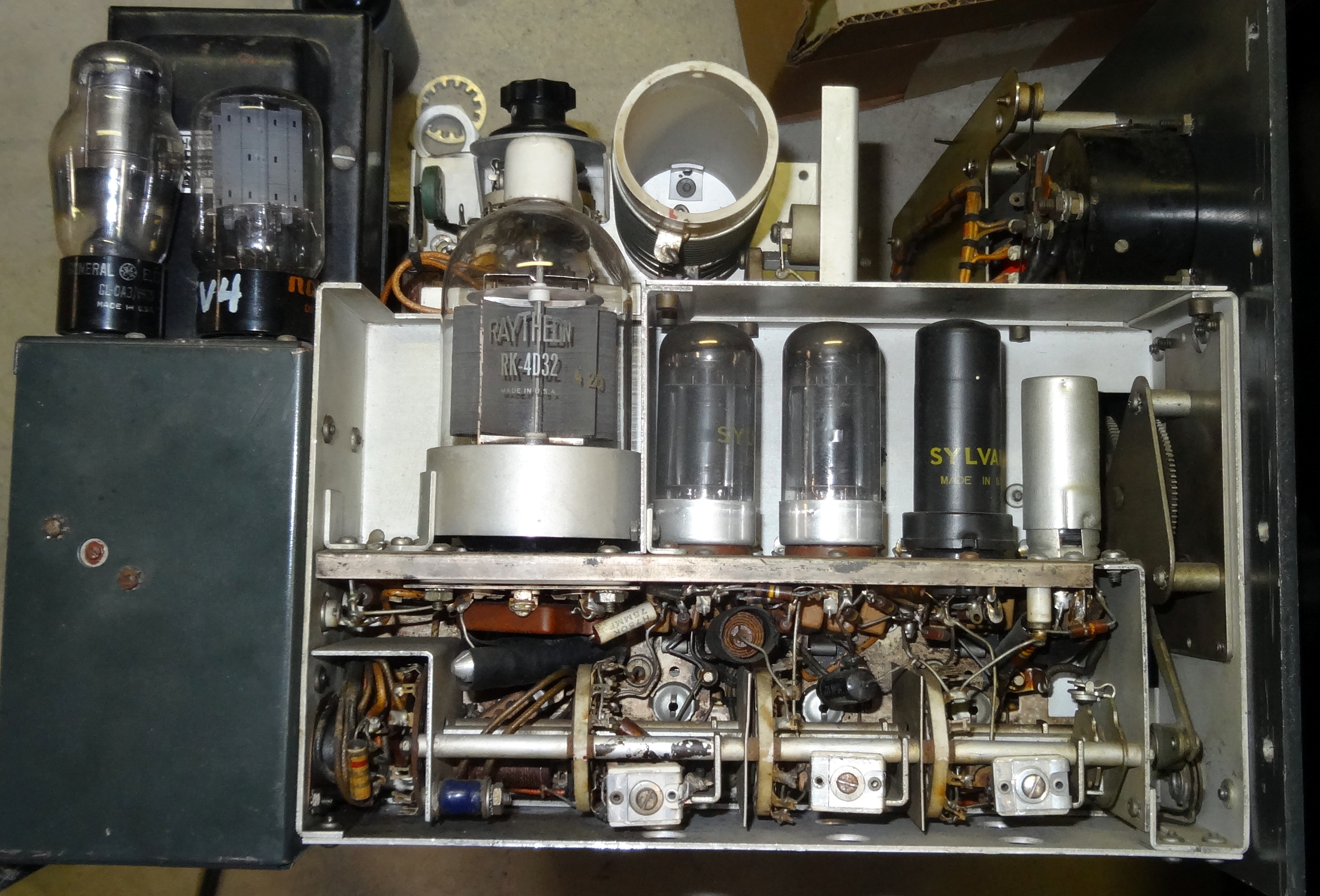 RF Section with 4D32 final.
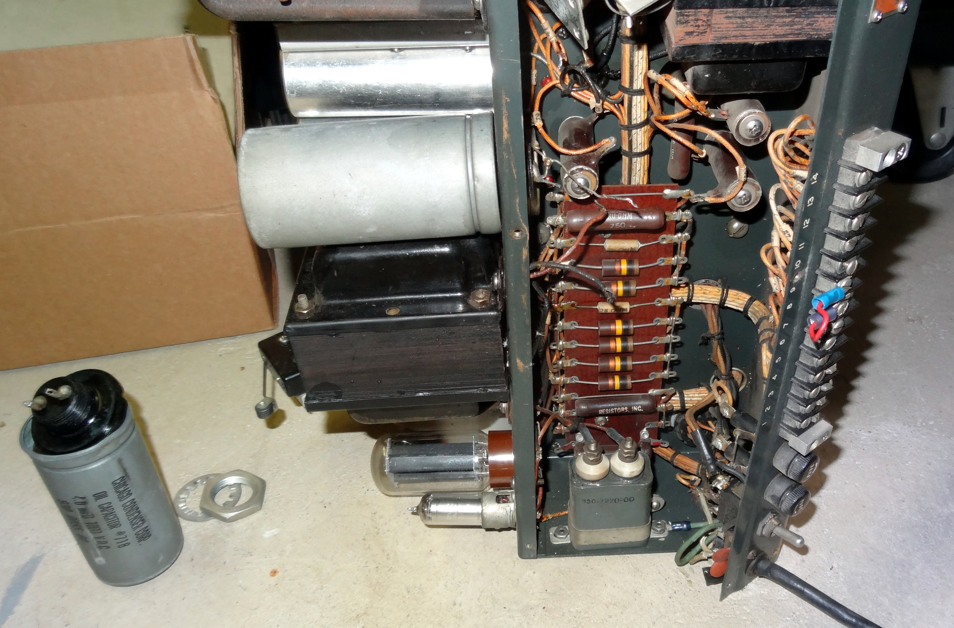
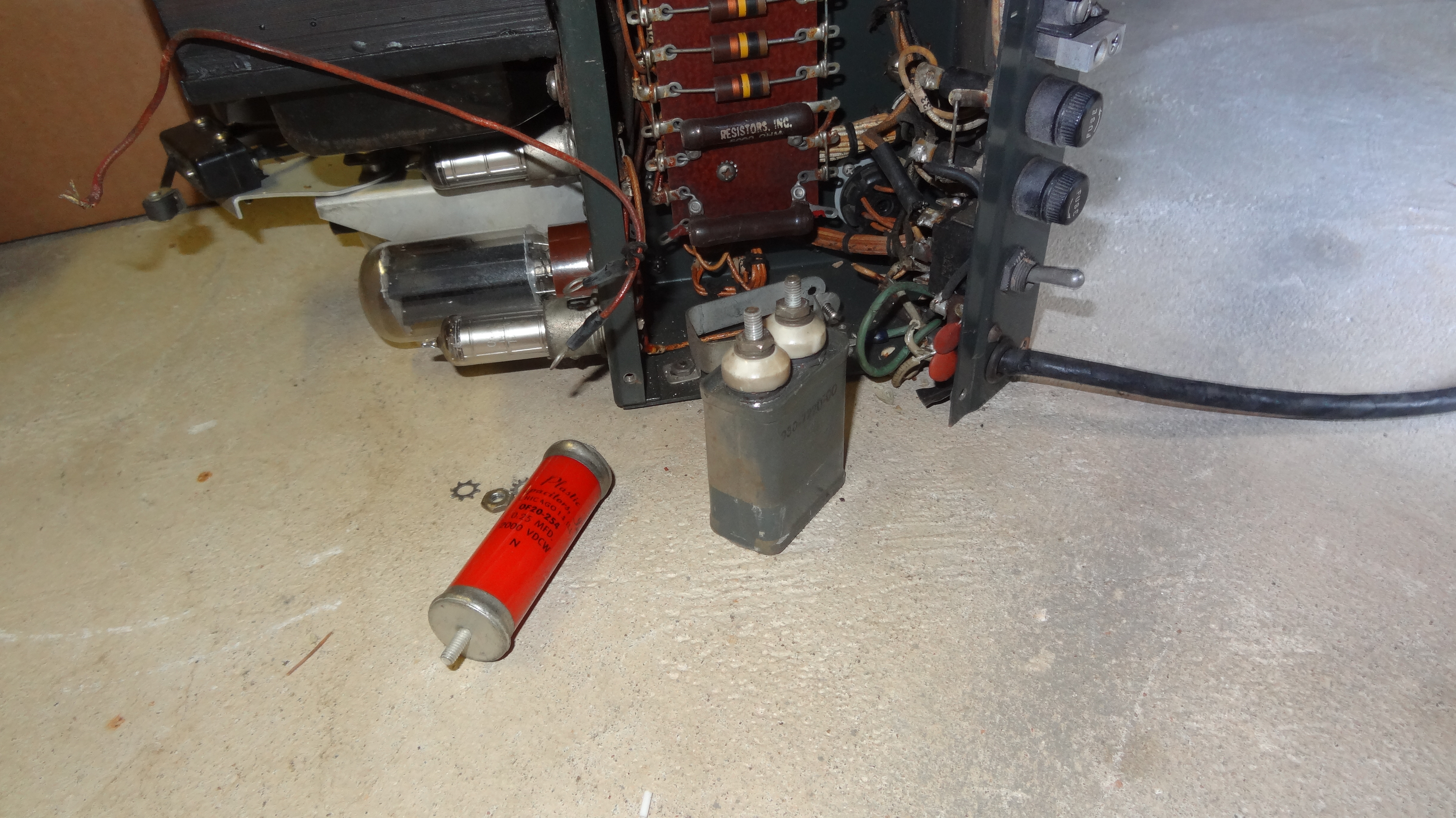 Transmitter still on the floor. HV choke resonating oil capacitor removed. The red capacitor on the floor would have been a replacement for it but way too large.
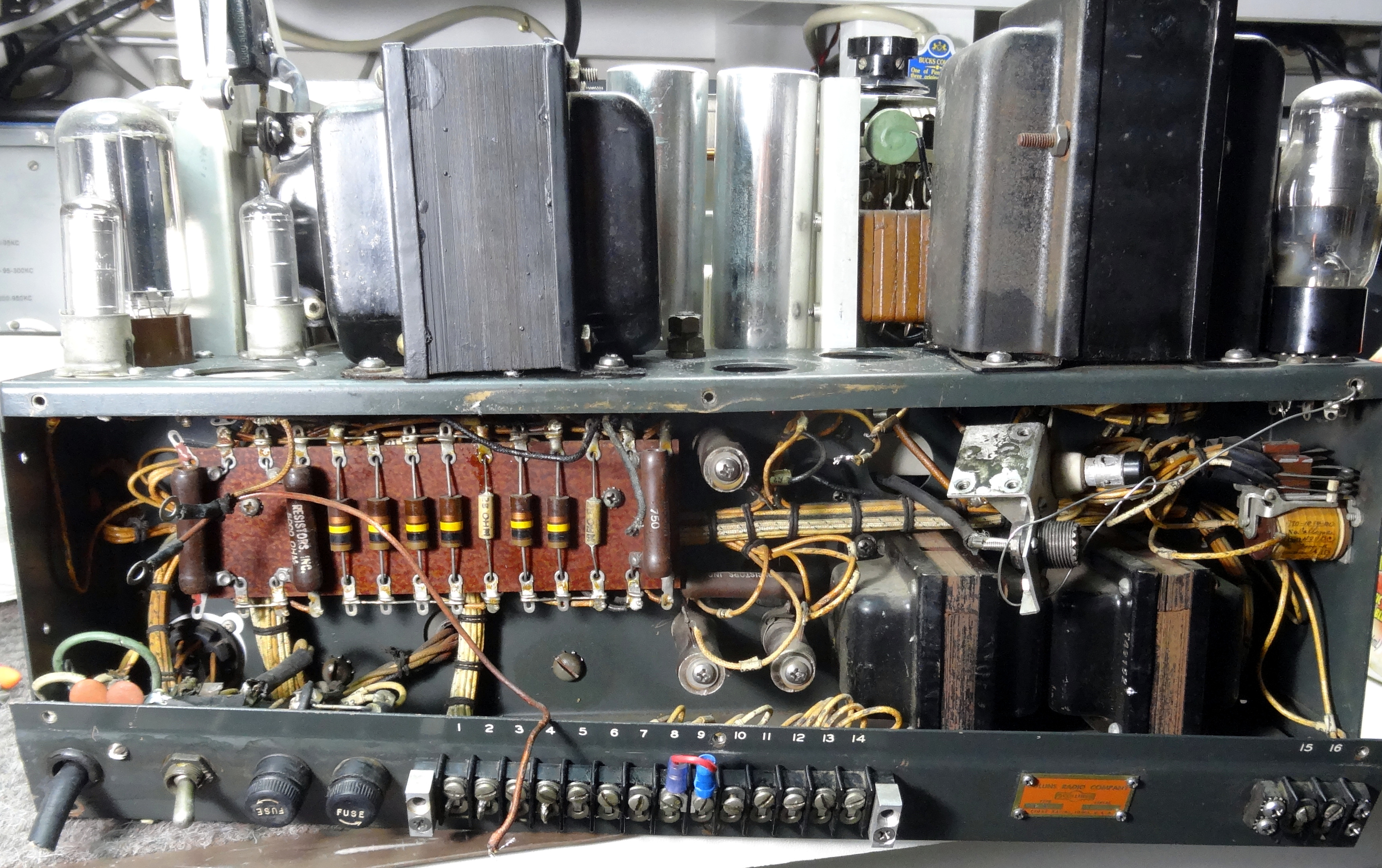 Finally up on the bench. 100+ pounds and back brace! Line cord cut off and ready for some restoration.
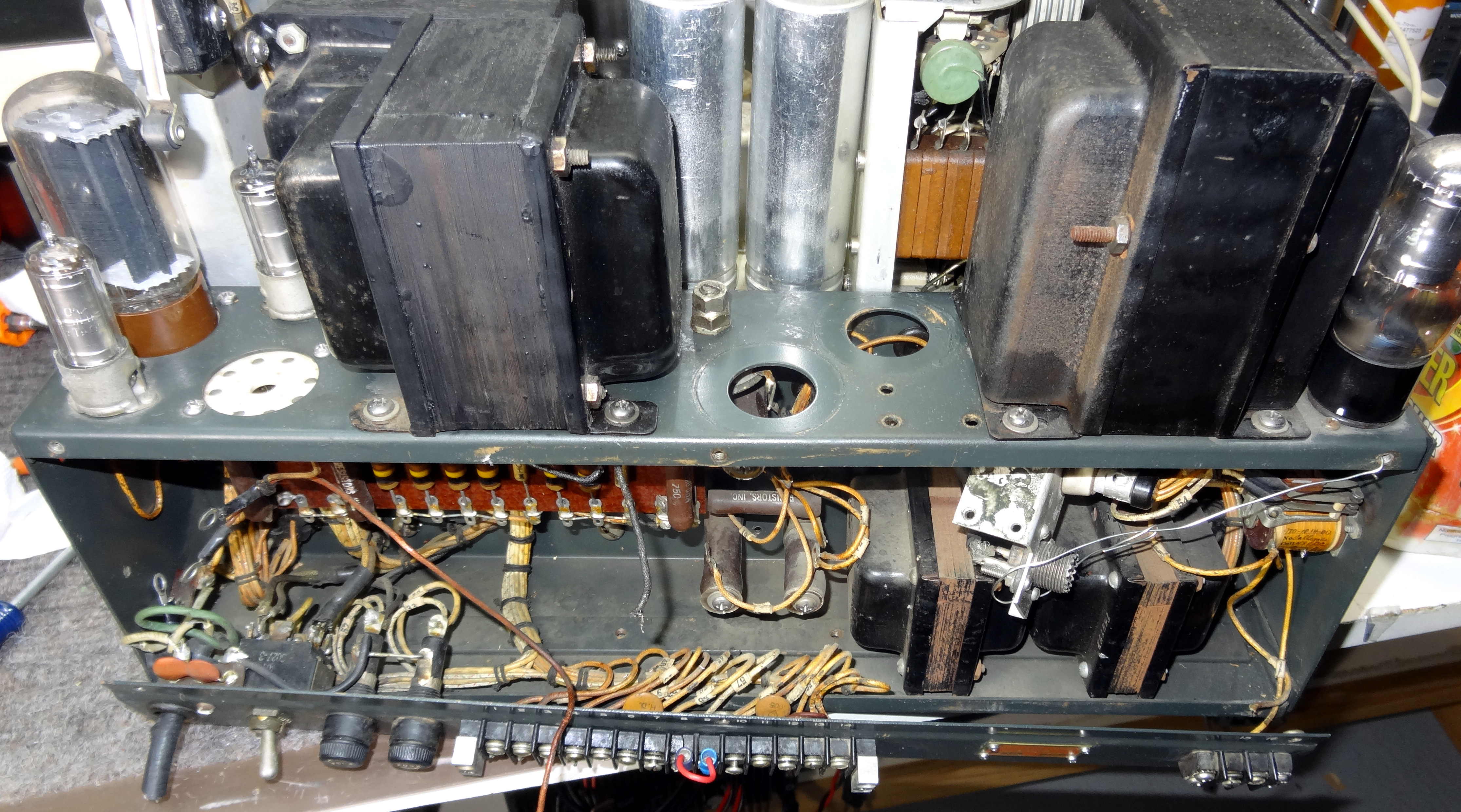 Rear view, both HV oil capacitors removed.
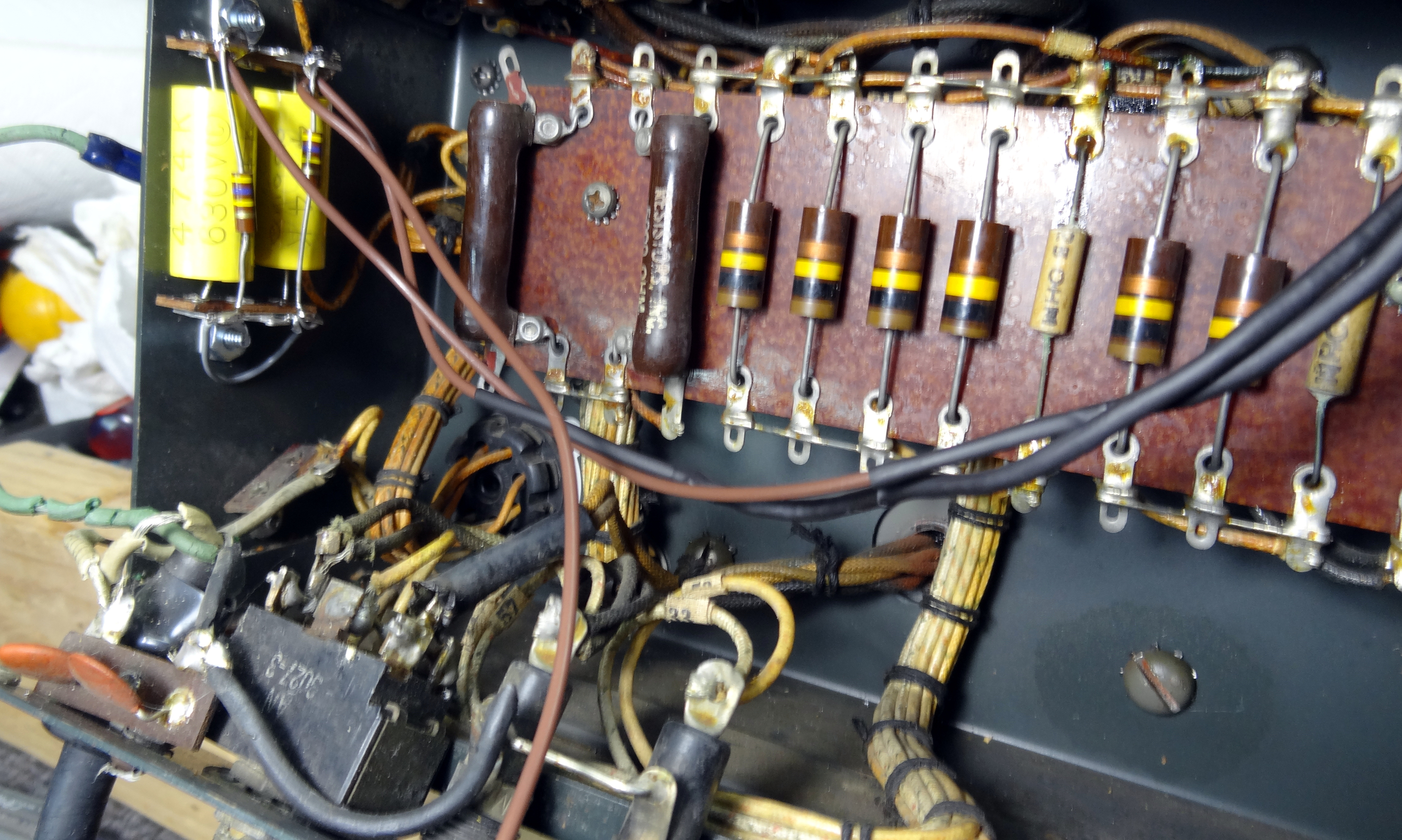 HV choke resonating capacitor replacement. Two 630V .5uf caps in series with equalizing resistors.
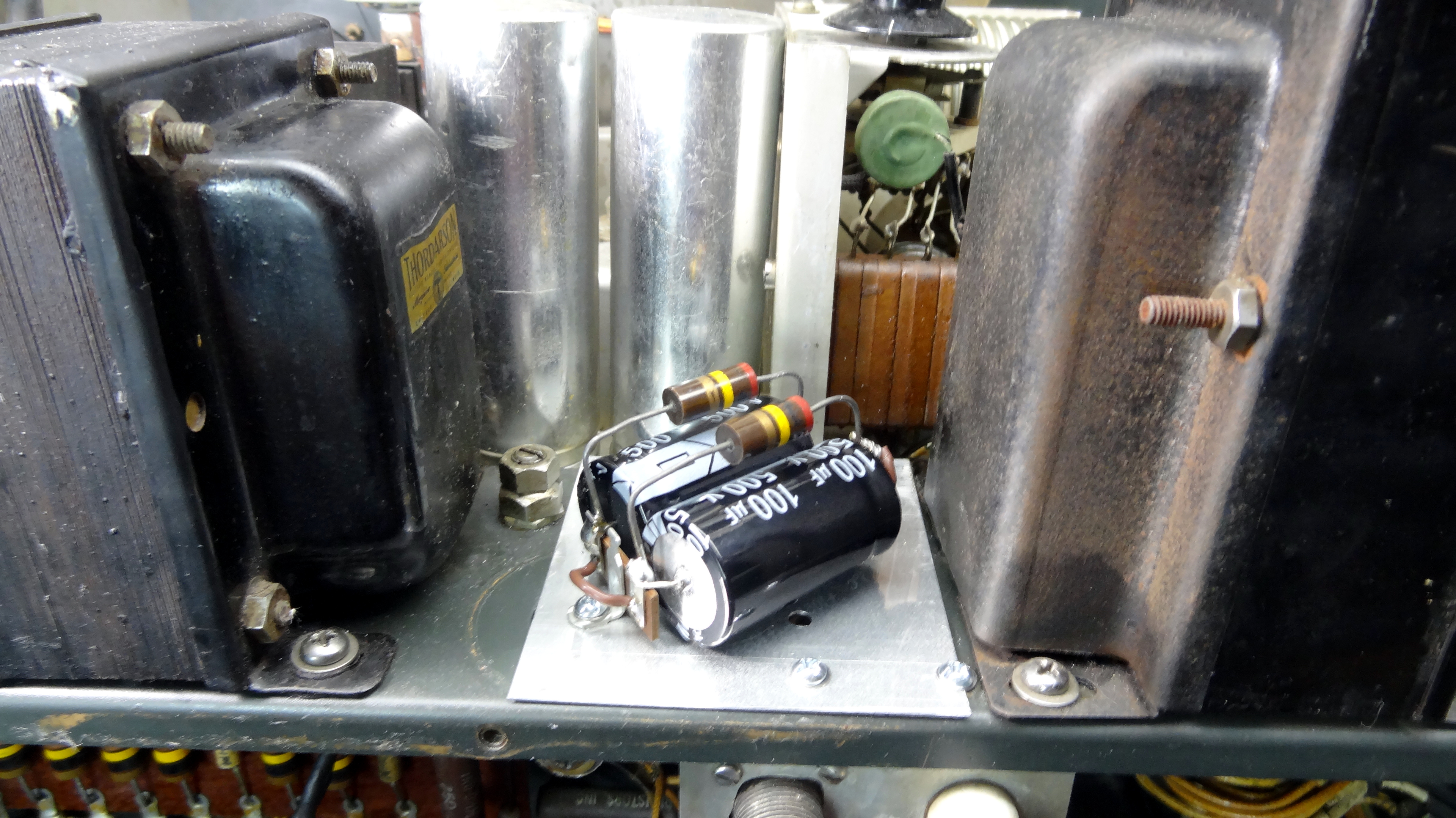 New HV Capacitors and equalizing resistors. Two series 100uf@500V replaces two 4uf oil capacitors. They are mounted on an aluminum plate to cover the original capacitor holes.
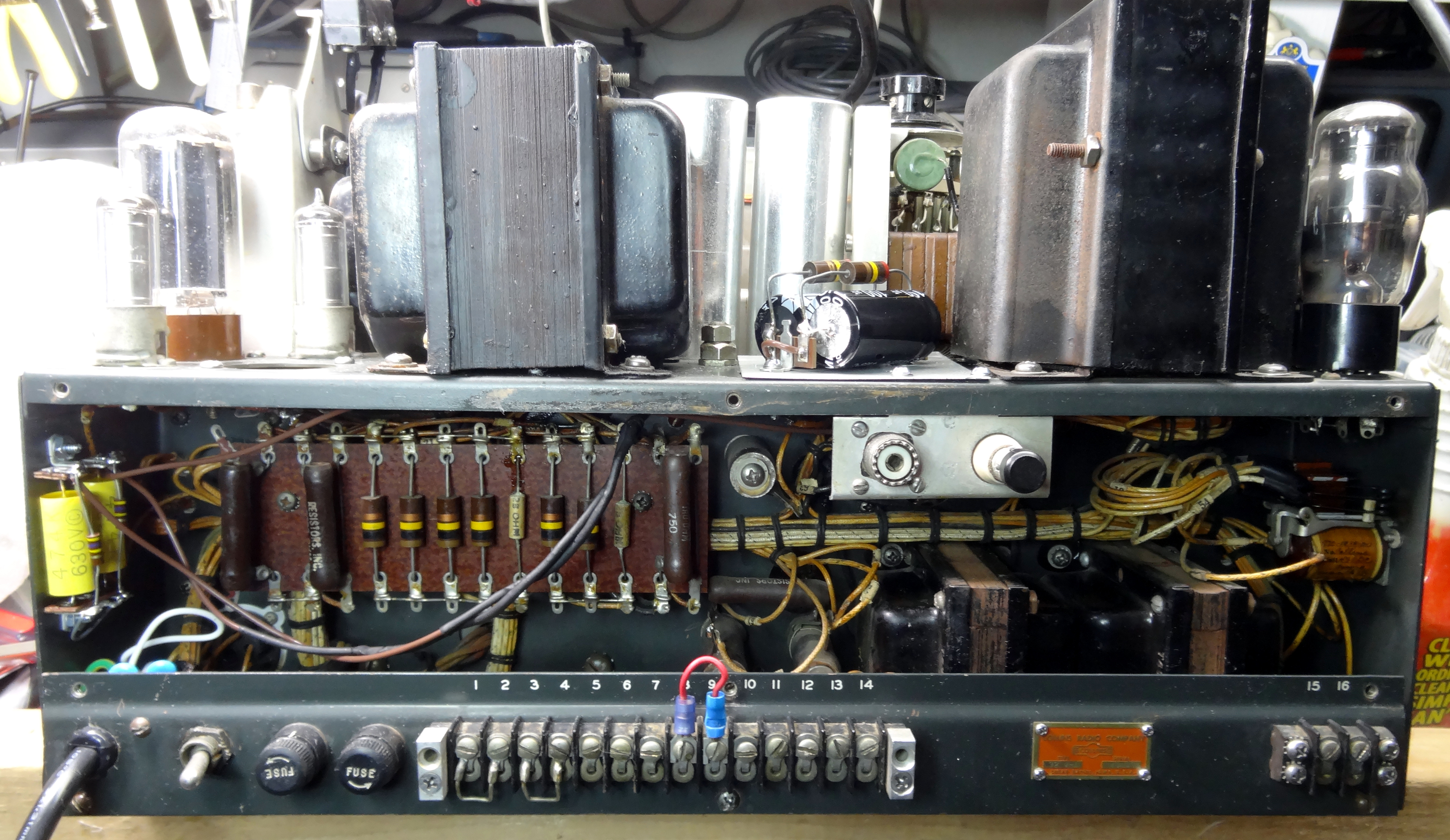 View shows back of transmitter with new line cord and strain relief. Also new line safety bypass capacitors.
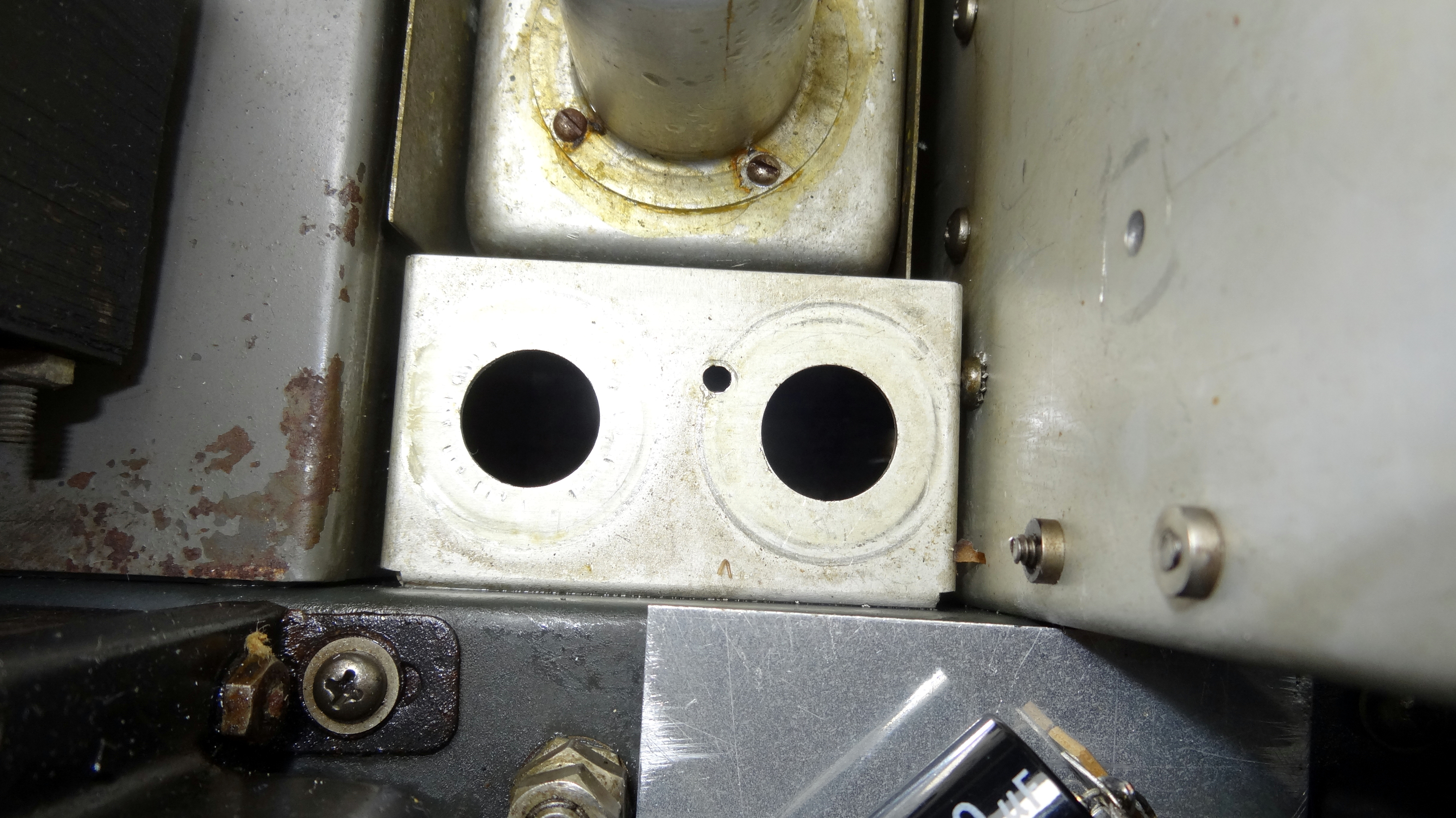 Top view of removed LV oil filter capacitor openings.
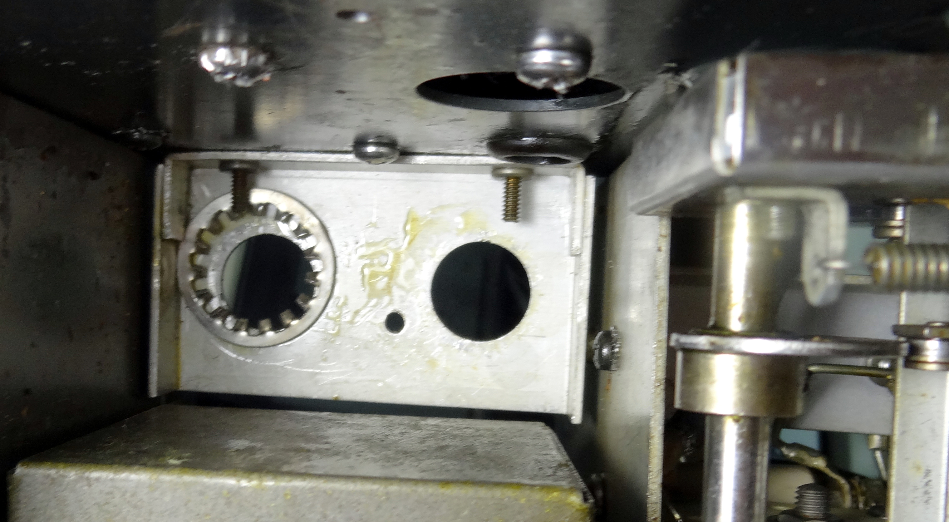 Bottom view of removed LV oil capacitor openings. One had started leaking and needed chassis cleaning.
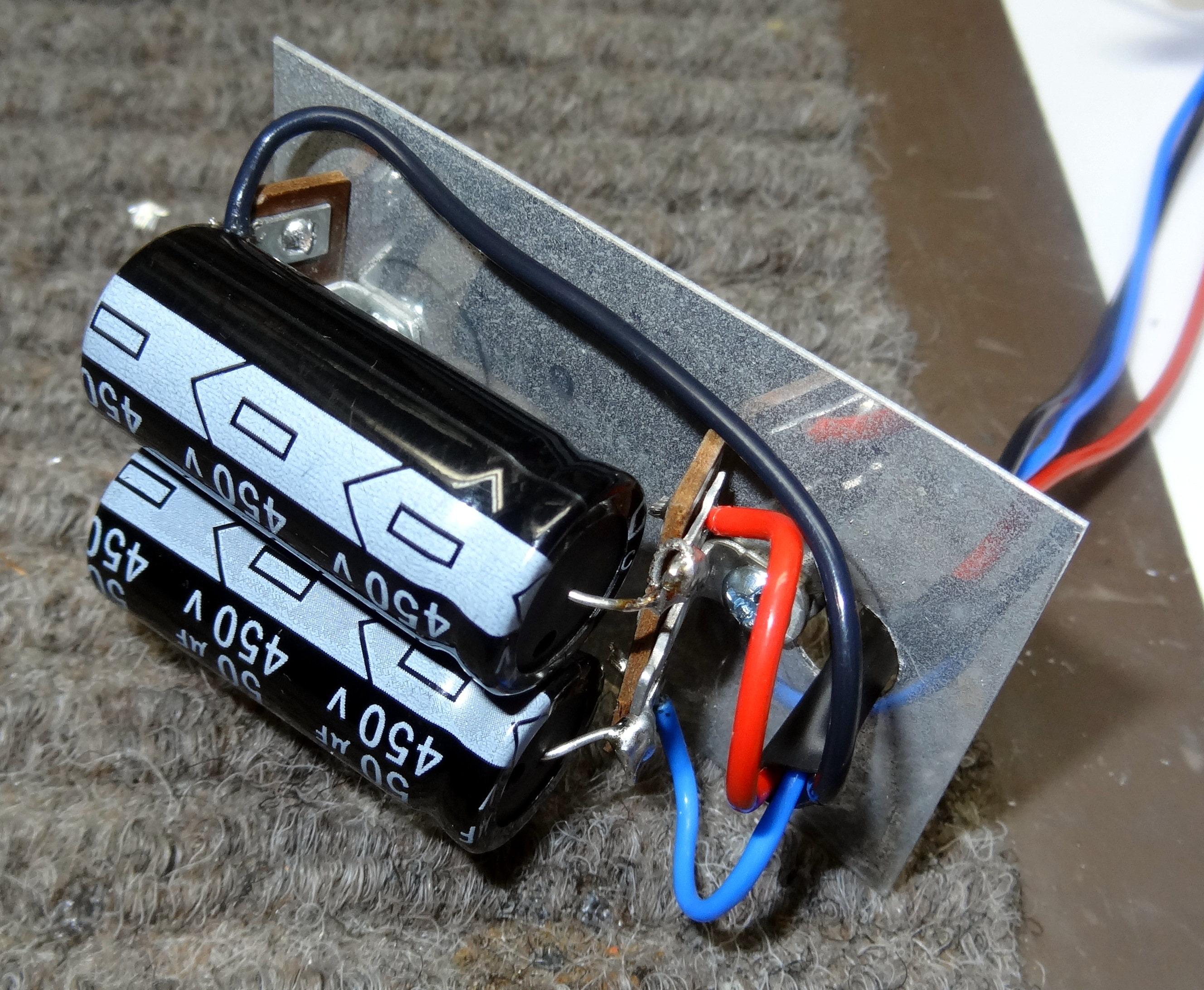 New LV filter capacitors on aluminum plate. Two 50uf@450V replace two 4uf capacitors. Wires are routed down and through the back power supply opening. Note the negative of these capacitors is floating to for negative bias. Former oil caps had a rats nest of several negative leads at the capacitors. These were brought back into the back power supply and tied together with the black lead of the LV capacitors.
Now we move on the the modulator section were all the oil caps were removed. I should take a minute and tell you why I think this is a good idea. They either have or eventually will leak. The oil makes a real mess in the radio not to mention its possible harmful properties. Yes, you could go through the trouble of remove all of them opening them up, cleaning them out,. a real messy job, and installing new modern capacitors inside. For the most part these oil caps are not bad electrically but the seal will eventually fail and then you have a mess to clean up. In this 32V-1 there were several leaking. I might add that the removal of all of the oil caps results in about about a 10 pound reduction in weight since the replacements have negligible weight. It also makes for a much cleaner appearance and a substantial increase in capacitor values. Back in the mid to late 1940's when this was designed the availability of small high value capacitors did not exist. Many of the parts were war surplus and values, especially in filtering applications were extremely low compared to standard practice and availability of capacitors today. I never touch front panels or do anything to compromise the performance of a radio but rather do things to improve it by today's standards. This greatly improves the life of the product.
 Removing the oil capacitors from the modulator section. The brown discoloration shows oil leakage.
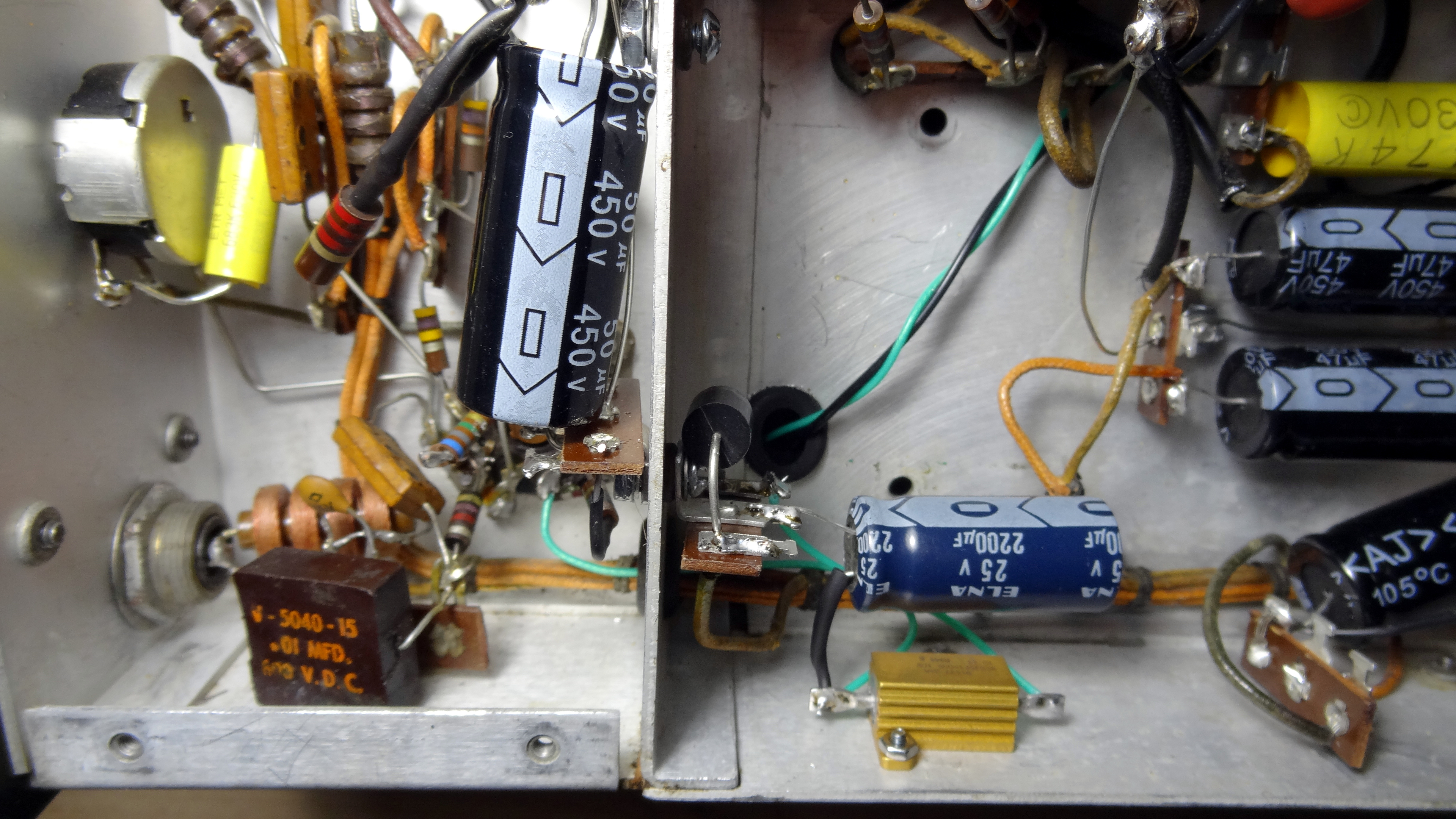
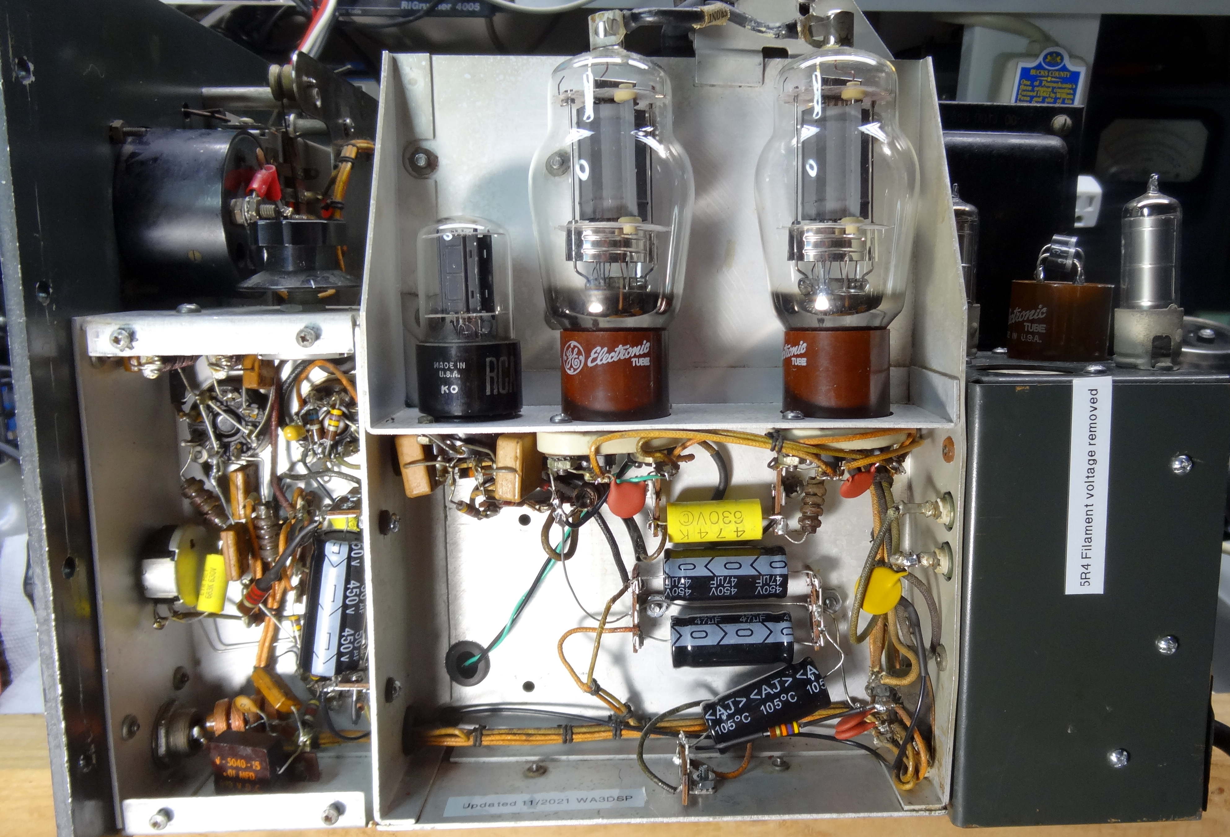 And the new capacitors installed. Note the additional filament bypass capacitors on the 807's. The grommet and wire to the filaments feeds the replacement LED green front panel LV power indicator.
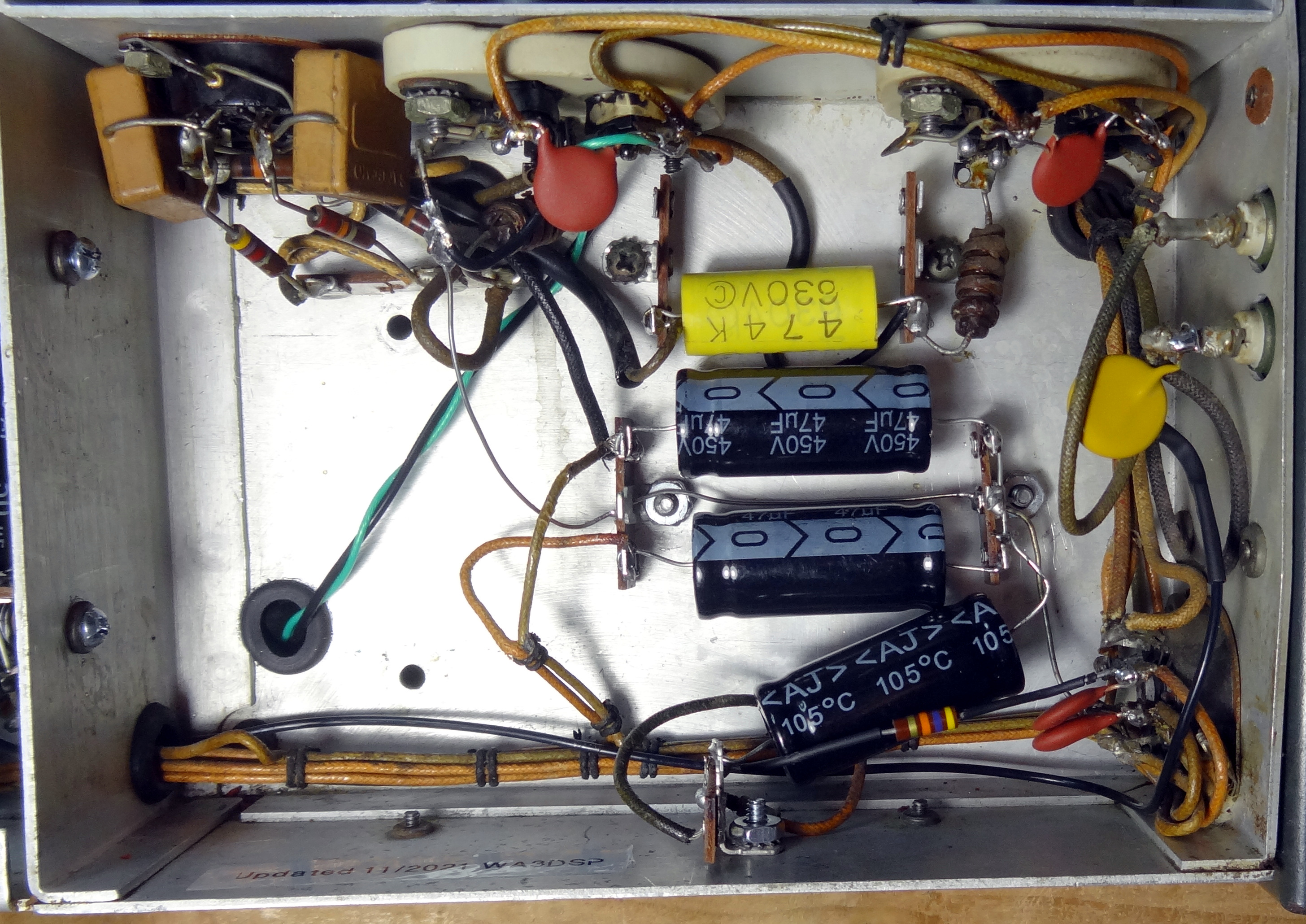 High level modulator section.
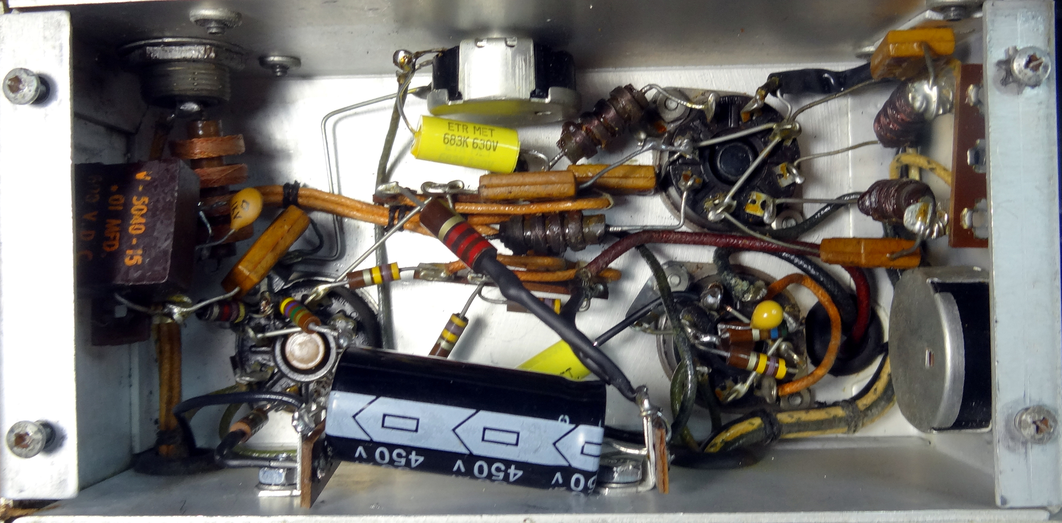 Low level audio section.
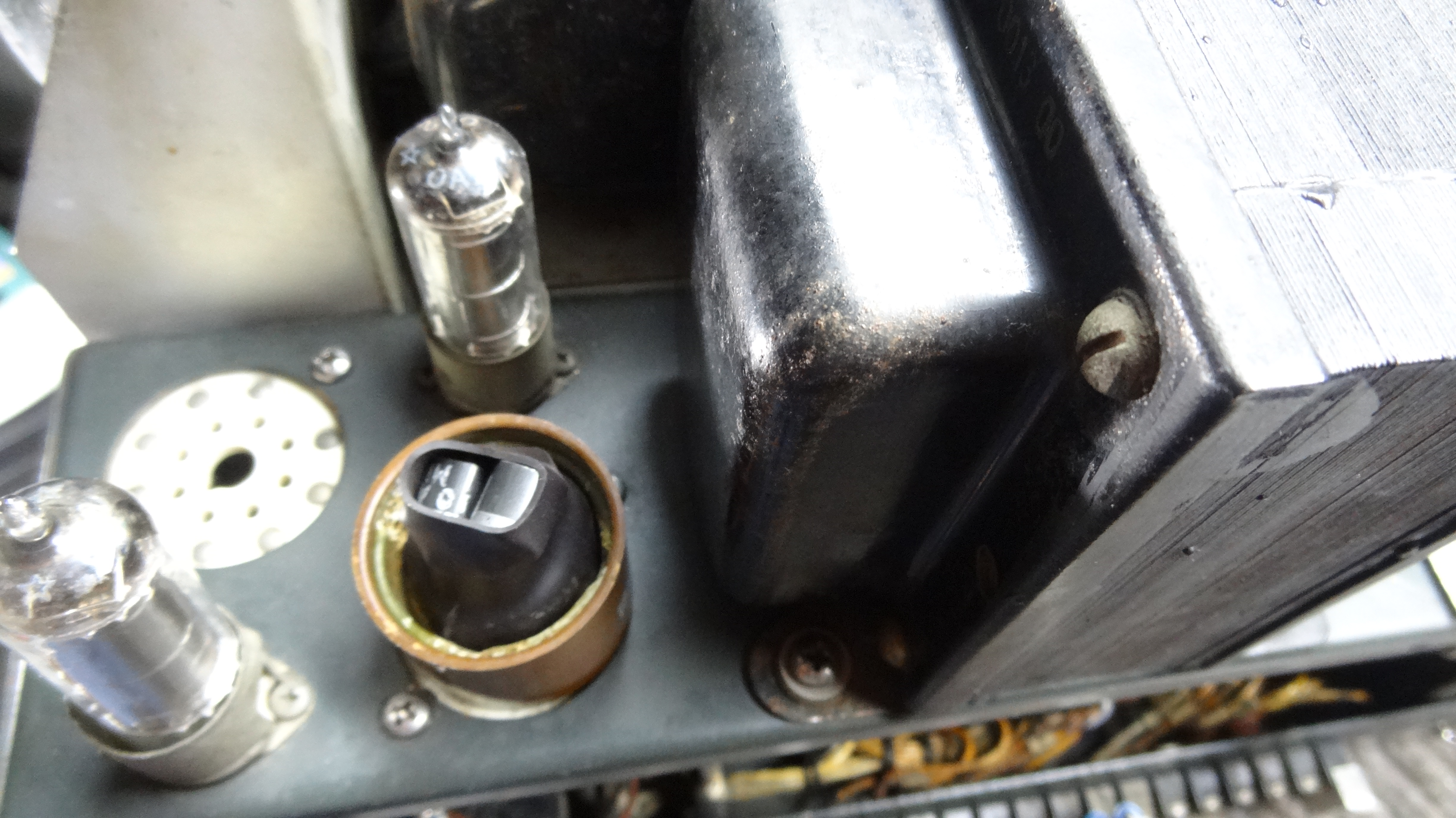 HV rectifiers - 5R4's removed, filament lines to transformer removed and used for low voltage DC keying circuit. Replaced with three 3A 1000v diodes in series per leg. Either socket could be used.
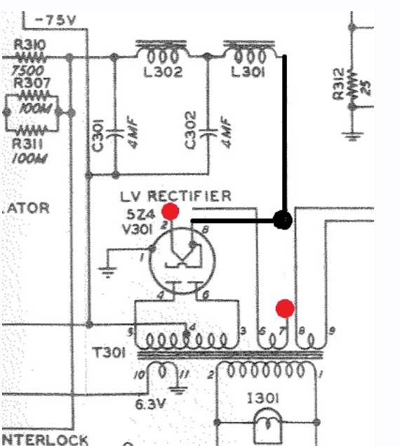
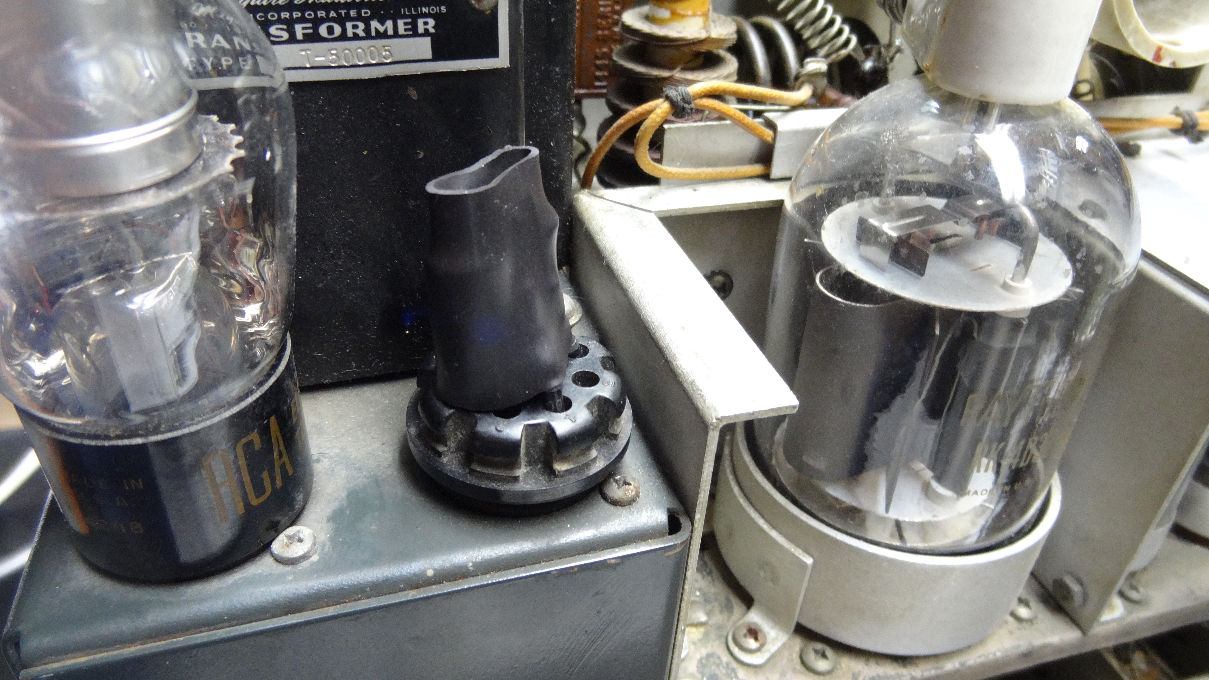 Low voltage rectifier 5Y3 removed and replaced with two 1A 1000V diodes per leg. Two 330 ohm 2W resistors in parallel in series on output. 5V filament wires pin 6 and 7 removed from transformer and tied together. See schematic for details.
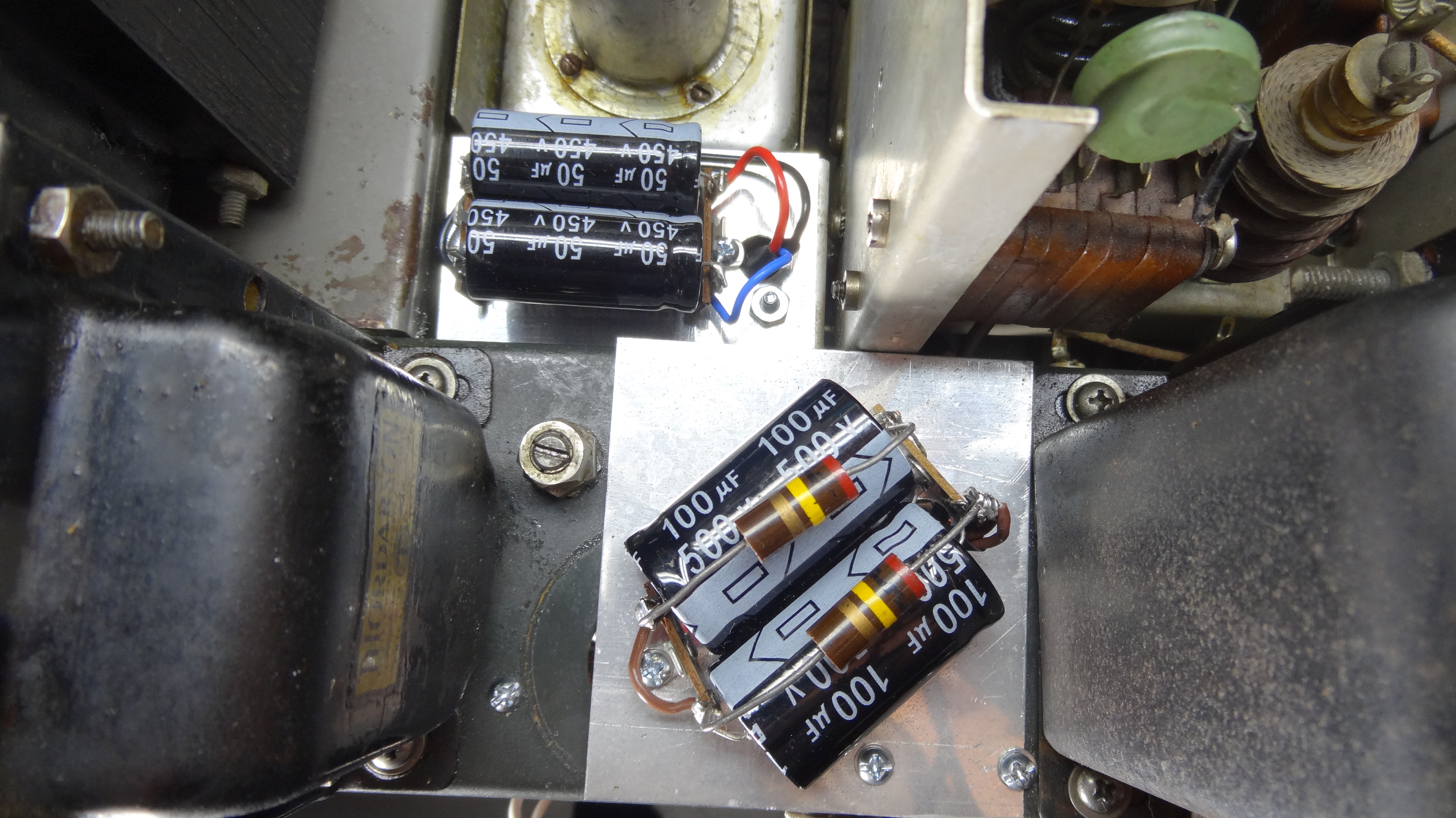 Top view of both new LV and HV filter capacitors.
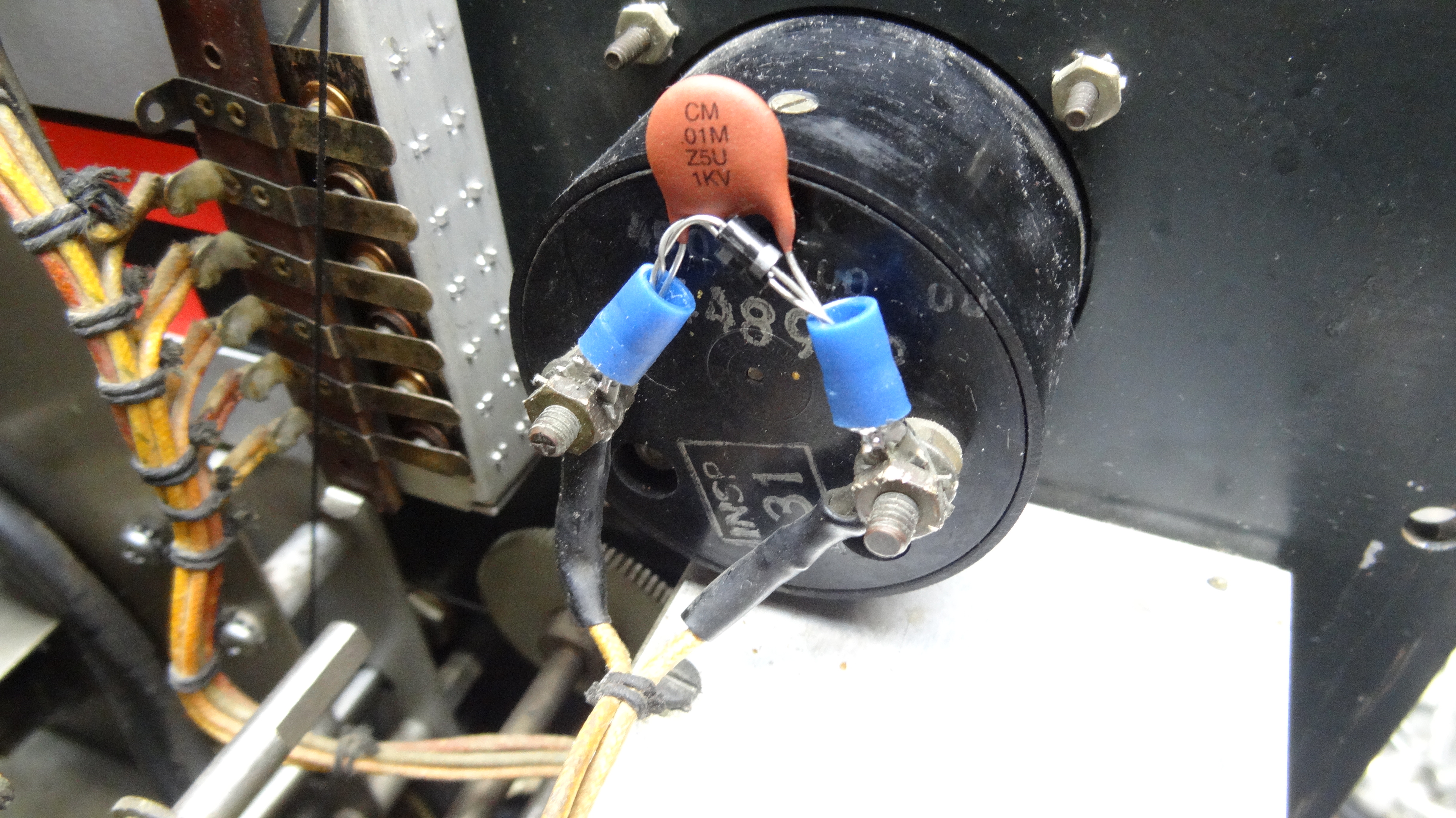 .01 capacitor and back to back diodes on both meters.
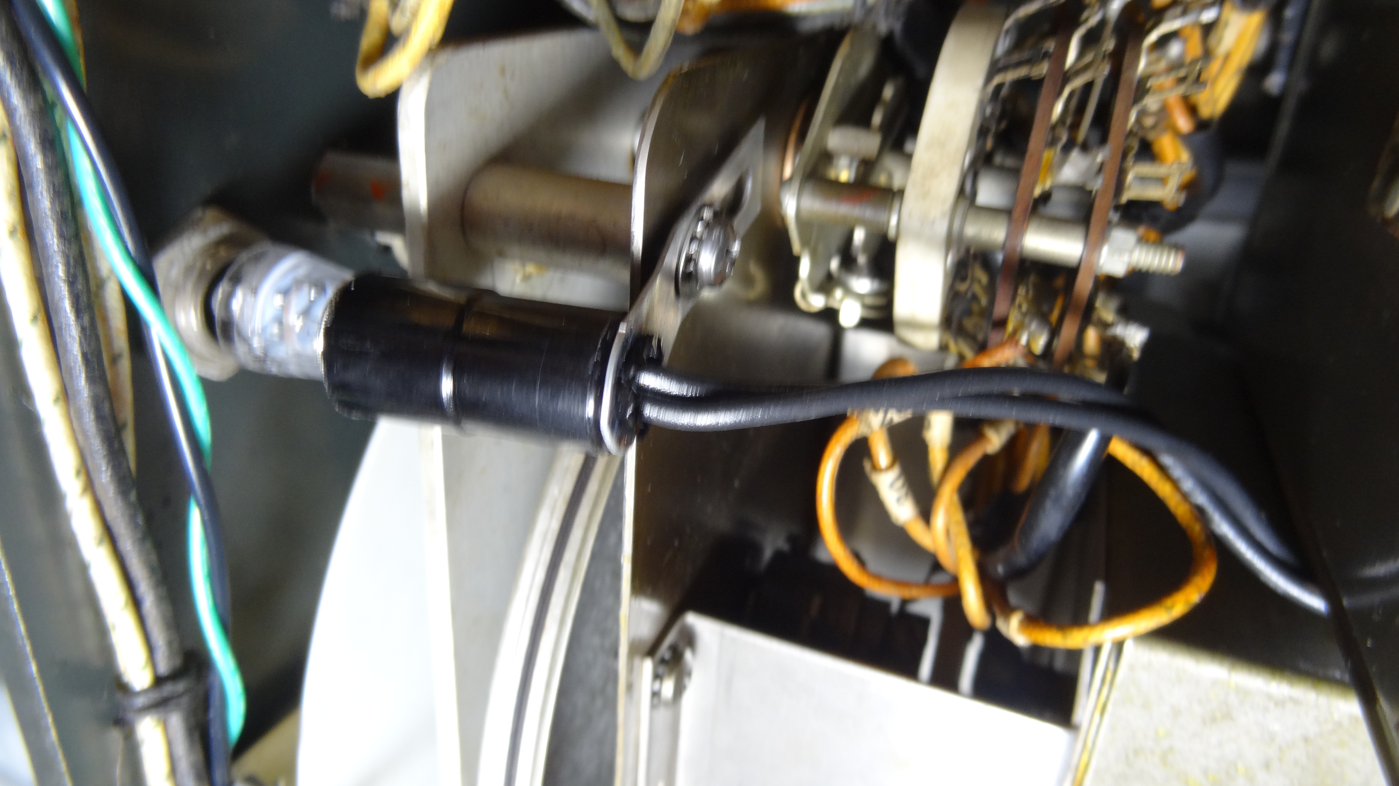 High voltage red front panel indicator changed to LED. This was a bayonet LED replacement. Bayonet socket added. Lens remains original. See schematic for connections.
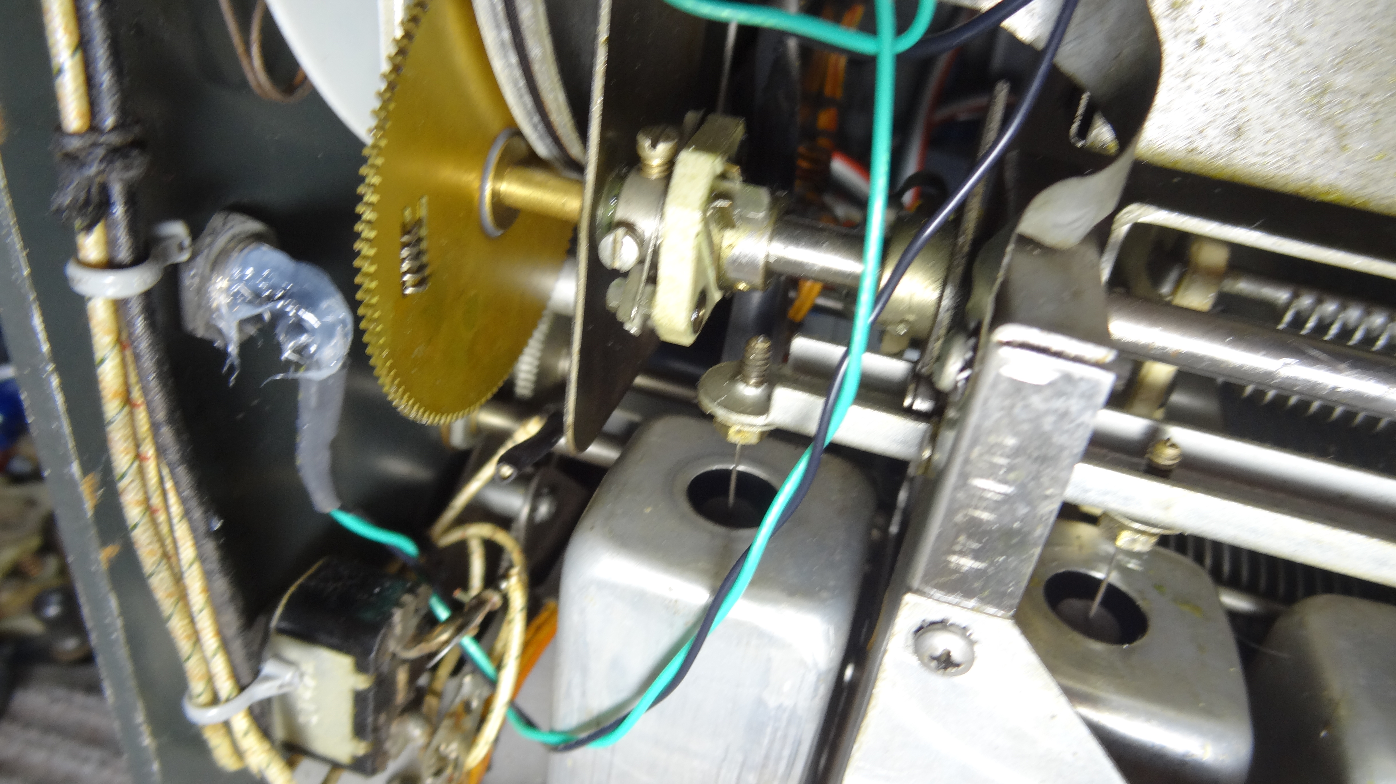 LED for green front panel indicator built from high output white led and resistor running on 6.3VAC derived from 807 socket in the modulator. Positioned and held in with silicone sealant. Lens remains original.
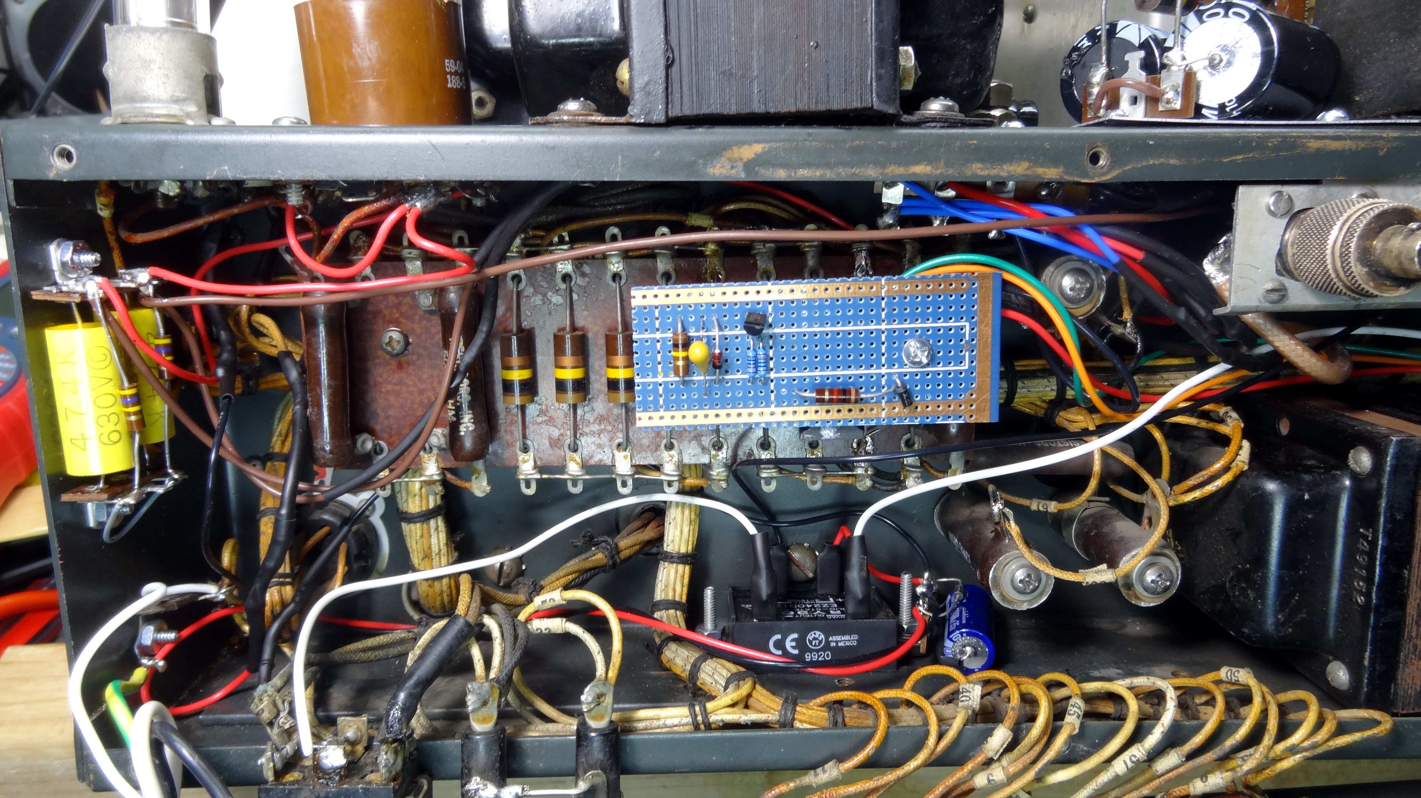 Back view with bottom panel down. Shows low voltage PTT relay keying board mounted on a standoff and SSR (Solid-state relay) and its power source for high voltage primary keying. See the schematics for details.
Items Updated and Added in the Restoration
- New line cord and strain relief
- Safety line bypass capacitors
- Solid-state LV supply
- Solid-state HV supply
- LV Solid-state relay keying for PTT
- Solid-state relay keying of HV
- LED's for LV and HV front panel indicators
- back to back diodes and bypass capacitors on panel meters
- Removal of all oil filled capacitors
- Electrolytic Capacitors - 100uf@500V for HV
- Electrolytic capacitors - 50uf@450 for LV
- Electrolytic replacements with much higher values in modulator
- Increased coupling capacitance in audio section
- Increased capacitance for driver cathode
- Added inverse feedback to modulator
- Fixed meter shunts to read proper voltages
- Added DC for the first audio (6SL7) filament
- Added MOSFET regulation for the PTO B+
The removal of the two HV rectifiers (5R4's) and the LV rectifier (5Z4) reduces the LV transformer load by 30 watts. It also removes heat from the 5Z4 with its bulb within a fraction of an inch from the transformer case. It is also important to remove the filament leads from the sockets to eliminate any higher voltages on those windings. In reading about the 32-x series it appears the LV transformer is a weak link although nothing definitive as to why has been noted in anything I have found. The LV transformer does get quite warm when the transmitter is left on for longer periods of time. Any load you can take off of it is beneficial. Knowing the open circuit DC resistances of the windings of a good transformer would be helpful in analyzing a bad unit but no one would disconnect all the wires to measure unless a 32V was a basket parts case and the transformer was good. If I had to guess I would say the problem is the 6.3V filament winding. It is rated at 9A and the total calculated draw is 8.75A in the 32V-1. You usually like to have a little more headroom than that.
I cut the 5V filament leads to the HV (5R4's) at the tube that is closest to the back of the transmitter. These leads were used with a diode and a filter capacitor to be used for the solid-state relay circuit. See the schematics for details. Cutting the LV rectifier (5Z4) can be done in several ways. For me it was easier to remove the two wires from pin 7 and one wire from pin 6 of the LV transformer and tie all three wires together. This make pins 2 and 8 of the original 5Z4 socket the output of the solid-state diodes, either or both pins can be used and it leaves no wires connected to the 5V output at pins 6 and 7 of the LV transformer. After removing the filament leads on the HV (5R4) I did the same thing, tying pins 2 and 8 together so either could be used as an output for the diodes. For the LV I placed two 330 ohm 2 watt resistors in parallel and in series with the output as shown on the schematic.
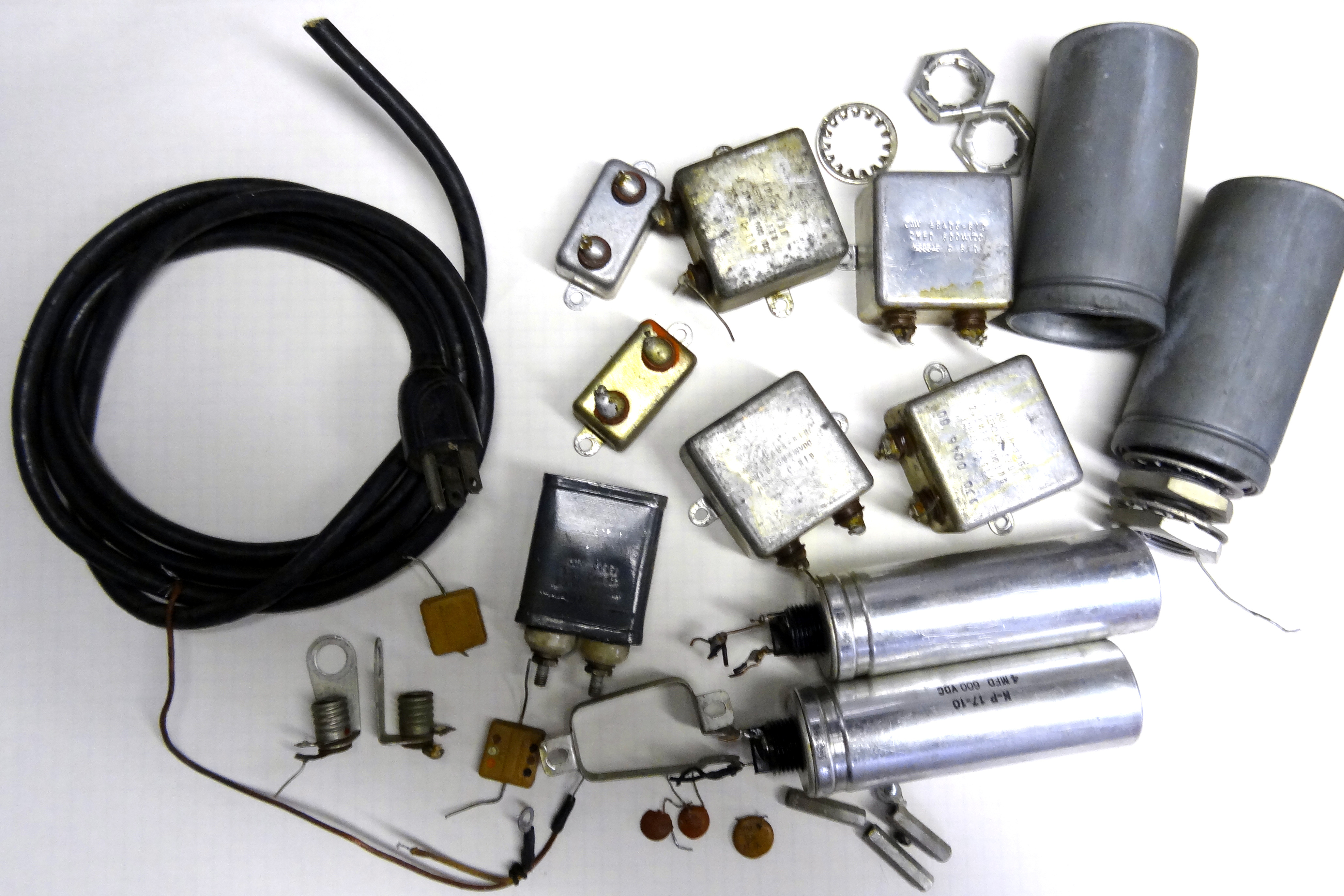 Don't you just hate it when you take something apart and you have left over parts! Well all kidding aside these were the parts removed and replaced with modern parts. This lightened the transmitter by about 10 pounds, did away with oil leakage, and improved the overall performance.
Final Results
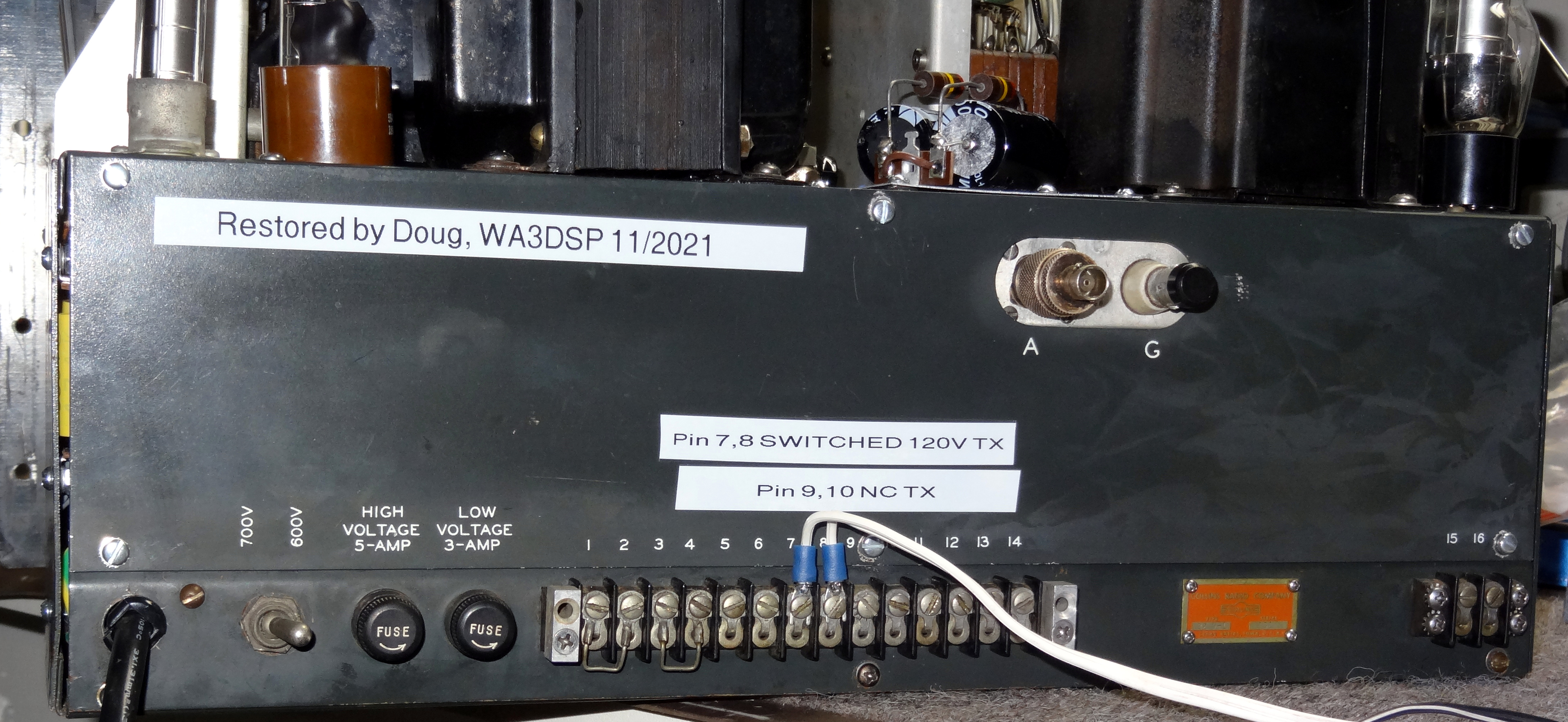 Rear panel with notes on changes to the pin functions. This terminal strip has hazardous voltages on it. I think it originally had a cover and I plan to fashion one to replace it.
I put the finally modified and restored transmitter on the air and got excellent reports on AM phone. There was some very low level hum that I need to track down. My suspicion is the unshielded 6SL7 first audio tube. With the changes in the audio section the low frequencies become more apparent. I suspect Collins rolled off the low end on purpose due to the higher ripple with the lower value filter capacitors. Overall I am very happy with the restoration. I plan to pair it up with the 75A-1 I restored for an vintage AM station. This pair is just a few years older than I am! Power output on 75 meters is a little over 60 watts on the 600V tap and over 100 watts on the 700V tap. I plan to run it mostly on the low tap to preserve the 4D32's life.
So why didn't the Collins engineers originally design it with some of these updates that I have done? I think the answer is the availability of parts. In 1946 when this was on the design table there were no solid-state devices. It would have been difficult to use a low voltage DC coil relay. They would have had to use a selenium rectifier and a fairly high value electrolytic for filtering. This would have required another transformer winding as the loss through the rectifier coupled with a 12V relay coil would mean you certainly could not use the filament winding. So the use of high voltage DC on the relay coil was a logical choice at the time. Today this would be a huge liability issue, having any voltage capable of shocking you available outside of the equipment in normal operation. For the 32V's this includes the back panel terminal strip which has LV, HV, and line voltage on various pins. The original design of switching the HV transformer primary with the relay seems like a failure waiting to happen given the size of the relay contacts. Maybe their use of two contacts in series helped. I would have thought they would have put an R/C "snubber" across the contacts. The thought of an inexpensive zero-crossing SSR to switch this would have been science fiction at the time but an easy fix today.
The 32V-1 cost $475 in 1947 which would be $6,737 in 2021 dollars. This is far more than most hams spend today for an HF transceiver with much more capability. Since it is estimated that 3600 of the 32V series were sold there obviously had to be some higher income people buying them. You also have to remember that this was just the transmitter. The ham had to buy a receiver also. If it was the 75A-1 at $375 it would be $5,319 in 2021. So it would have set you back the equivalent of $12,000 in today's dollars for a Collins receiver and transmitter station! Here is a list of 32V-x units manufactured.
Late Updates
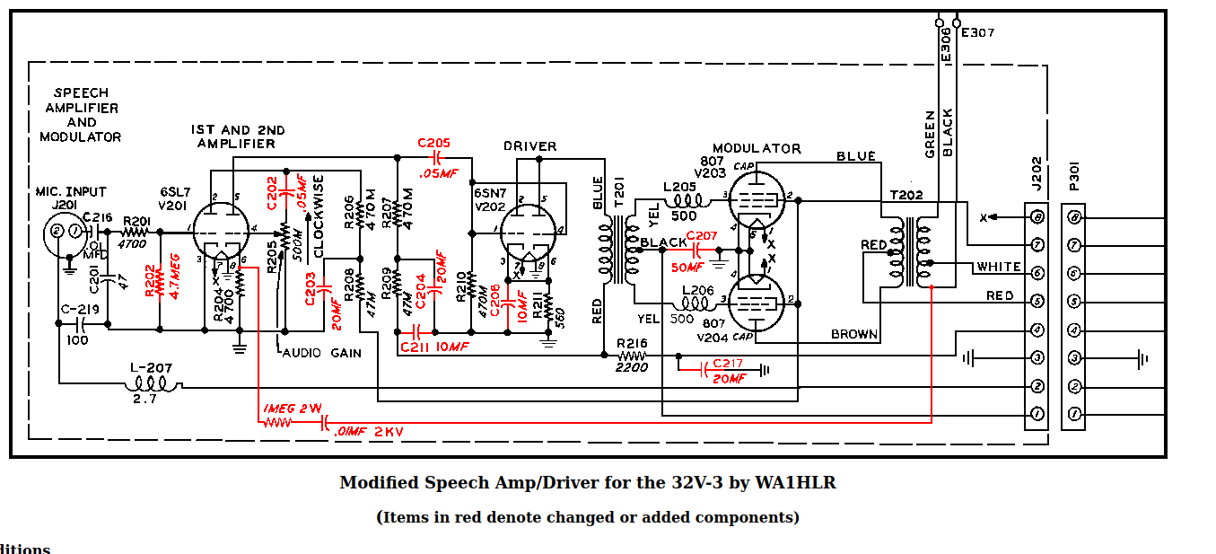
Here are some late updates on this restoration. First of all the WA1HLR schematic showing audio mods below has some errors. I would recommend NOT doing the inverse feedback mod. The other values are correct but in some cases I have made them larger. See my schematic for info. I had a report of good audio but a low level hum so I decided to DC the filament on the first audio (6SL7) tube. This completely cleared it up and some have said it is the best audio they have heard on a 32V. BTW Tim tells me he did not create the schematic I show here taken from AMFONE. Again disregard the inverse feedback shown in the schematic.
Another nagging problem was the PTO drift at keyup. It would drift a hundred cycles in seconds on each keyup. This is not much of a problem on AM but on CW it gave an un-pure note. Remember this is a 32V-1 and it has no regulation of the PTO B+ like the 32V-2 and 3 do using two series OA2's. I decided to add B+ stabilization using a MOSFET as I have in many other projects like the 516F-2 power supply. The results were very good showing only a few hertz drift at keyup and unnoticeable on CW. Photos of the mod below and shown in the schematic updates. PLEASE NOTE as shown in the schematic you must use an input diode to the regulator as for some strange reason Collins put negative bias on the B+ line for the PTO and three following stages putting -75 volts on the plates and screens when the transmitter was in standby (HV off) Looking at the 32V-2 it was done the same way but on the 32V-3 they dropped putting the bias on these tubes in standby.
 Updated photo showing components to add DC to the filament of the first
audio (6SL7) tube. Update also shown in the schematic of changes below,
Updated photo showing components to add DC to the filament of the first
audio (6SL7) tube. Update also shown in the schematic of changes below,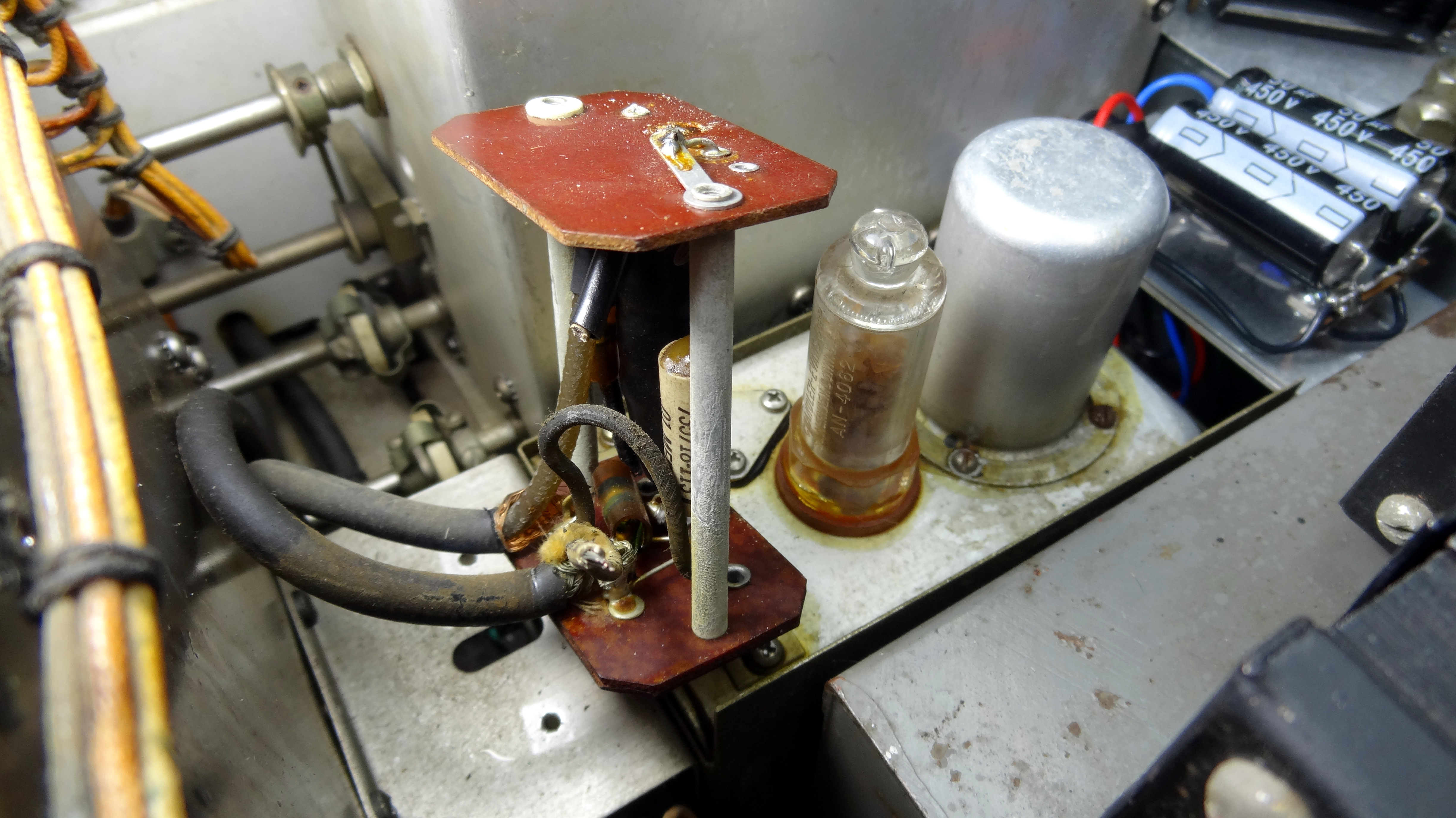 PTO cover removed. From front the right black entry cable has two shielded leads. One is filament voltage and goes directly to the plug. The other is B+ to the RF choke. Cut this line. It will feed B+ to the regulator.
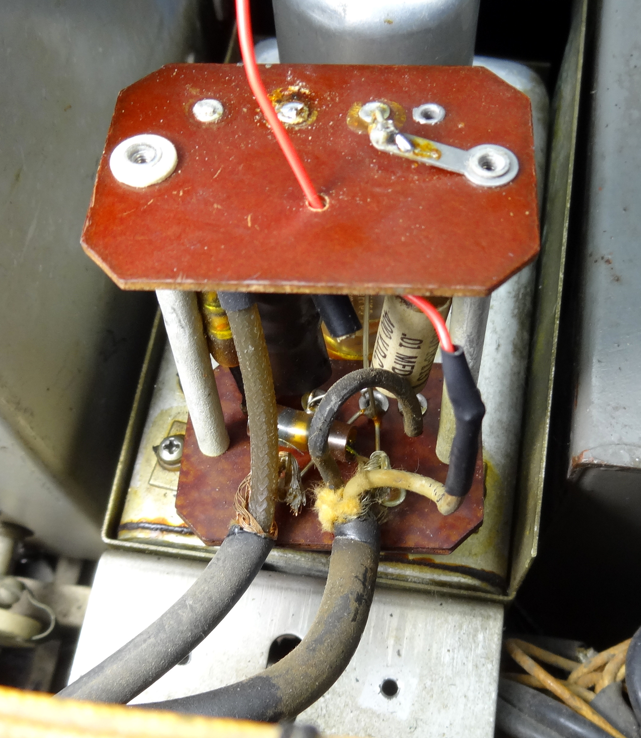 Red lead is B+ to regulator. It is attached to the B+ wire from the black cable.
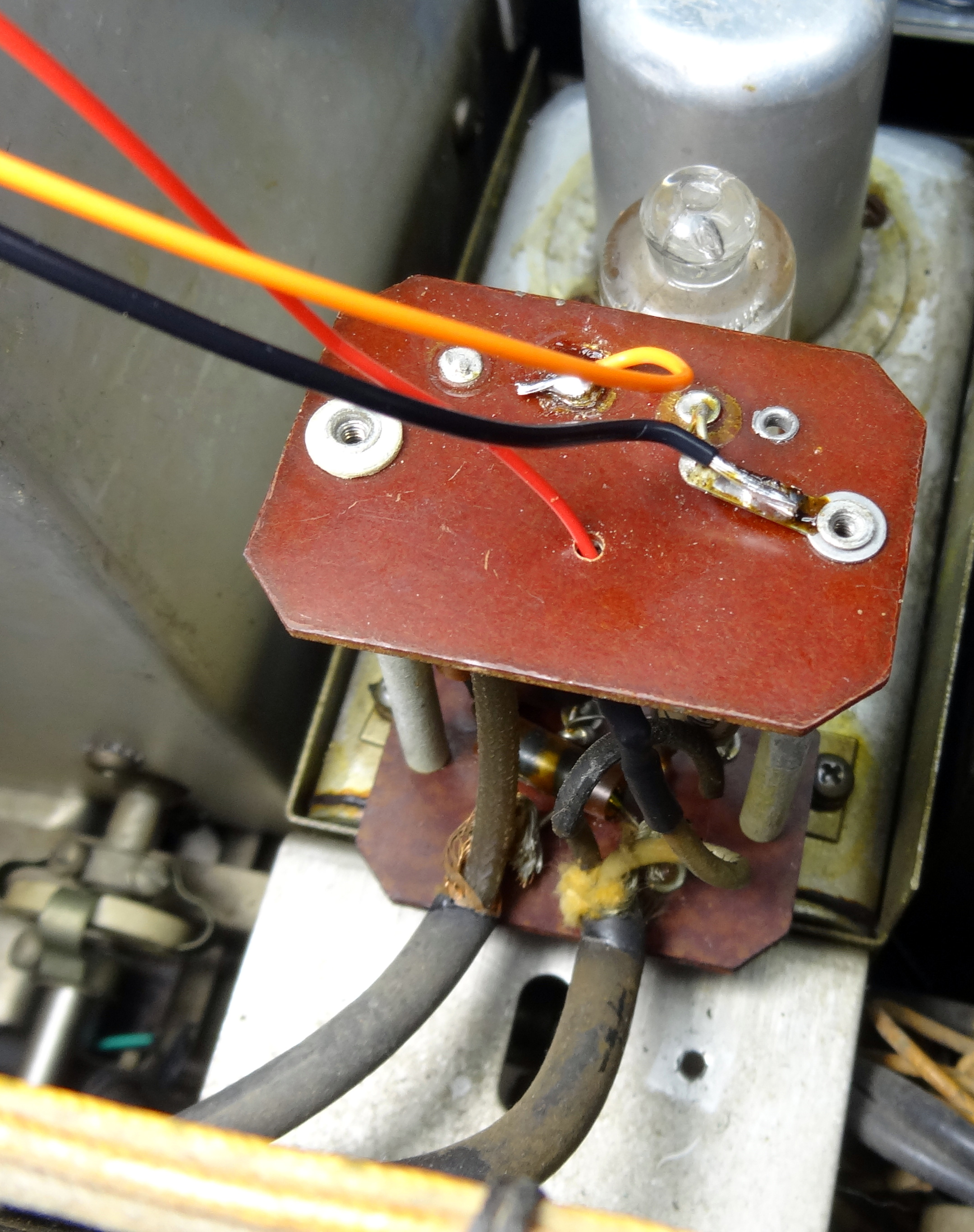 Orange wire (looks yellow) is connected to the top of the RF choke and black wire to ground.
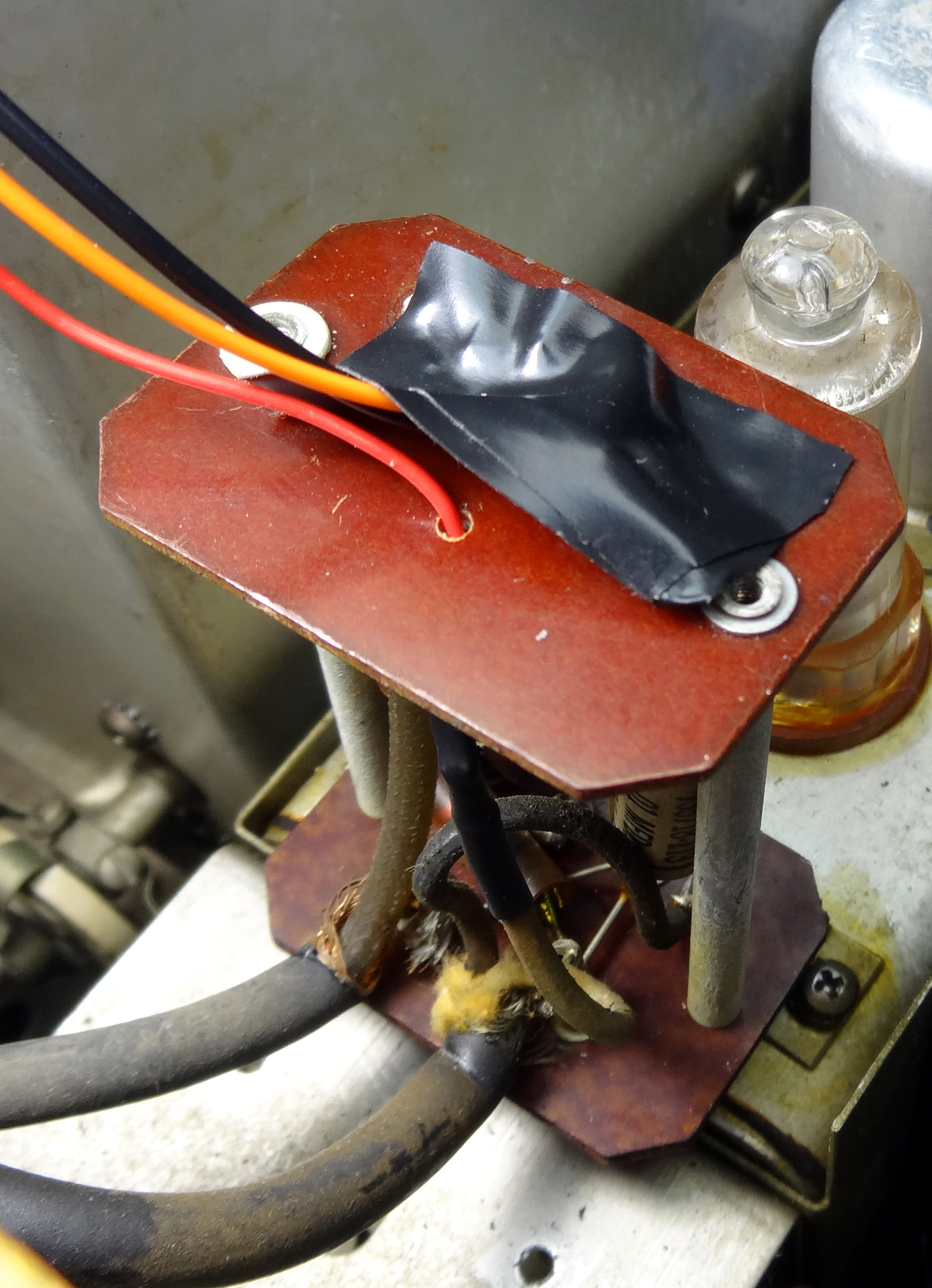 Tape installed over connections as a precaution.
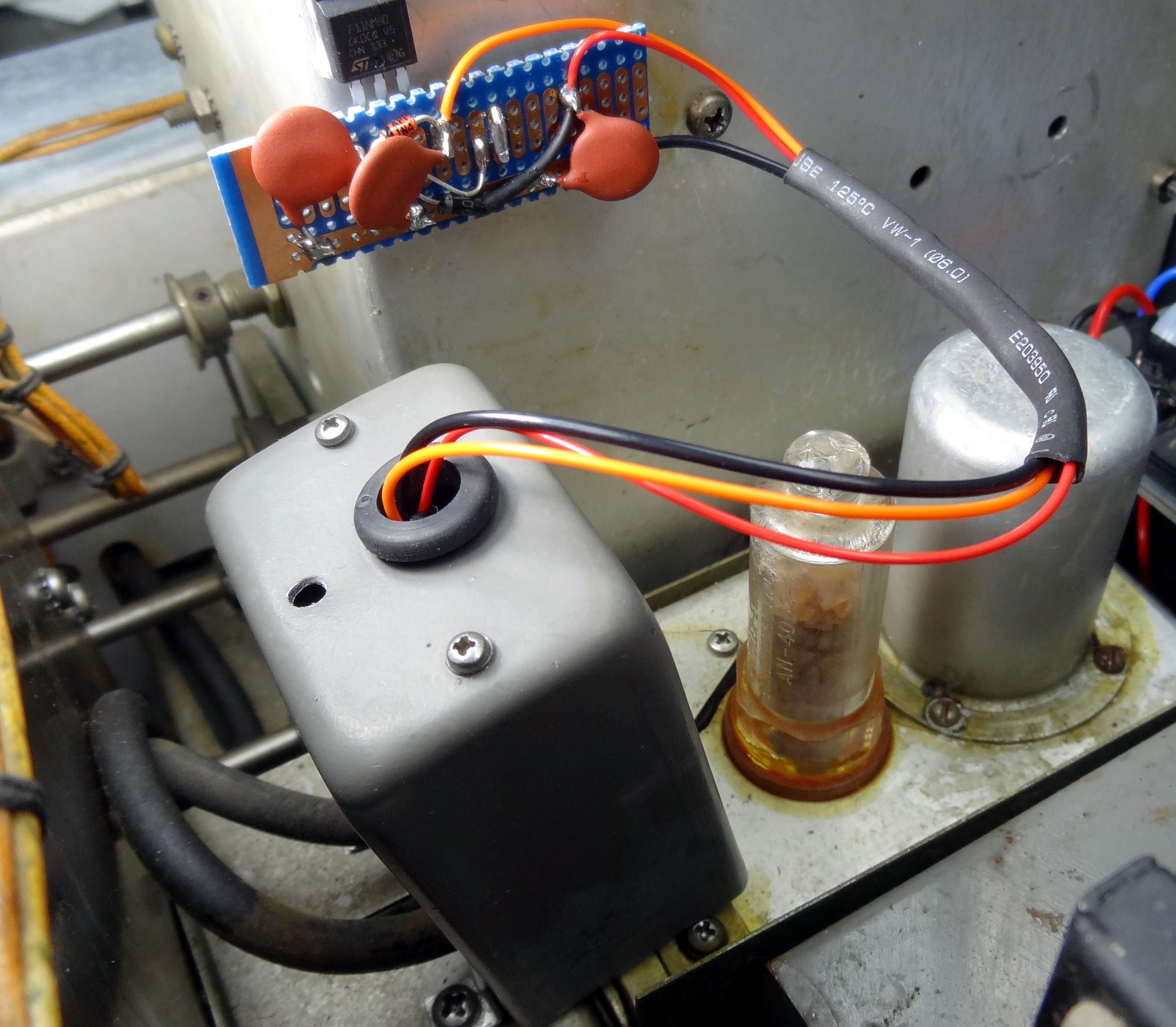 Cover reinstalled and regulator car attached to outside of RF deck in an existing hole. Heat compound used but the nice thing about this particular MOSFET device is that it requires no electrical isolation from the chassis. It is rated at 11A 850V.
32V-x Internet Links
- Original 32V-1 brochure
- 32V-1 manual and schematic
- Collins Collectors Association 32V
- Western Radio Museum 32V series
- Zen and the art of 32V Transmitter Maintenance
- QRZ forum discussion
- Hammond Replacement Transformers and chokes.
Links for this Project
- Example for removing LV transformer 5V from 5Z4 rectifier
Note that I did this differently, I removed 2 wires from pin 7 and one from pin 6 of the LV transformer and connected them together. This makes both pins 2 and 8 outputs for the solid-state replacment. - Audio modifications example
I used higher values in some cases here. See the modifications schematics. - WA3DSP schematic of modifications
- WA3DSP Keying adapter for 32V-1
- Hammond LV Transformer replacement
So far mine is good and it is not cheap so hopefully you won't need it.
Visit my hamradio web page for other amateur info and restorations. I can be found on the air at the Philadelphia Allstar hub node 27225, I am net control for the AWA Bruce Kelley net Fridays on 3837 LSB at 9:30AM Eastern and the QCWA Chapter 5 net Sundays on 3917 LSB at 9:45AM Eastern. .
73, Doug WA3DSP
This page last updated 12/18/2021
© 2021 - WA3DSP