Using the Baofeng 888s
as an Allstar Node Transceiver
The Changing BF888
Please read through this howto as the design of the BF888 has changed quite a bit over the last few years. When you order from Internet retailers there is no telling what version you may get. They are all good but will require different modification procedures. The latest one as of early 2017 is using a much smaller internal board. Photos and connection points for all of the known designs are shown below.
Introduction and Purchasing
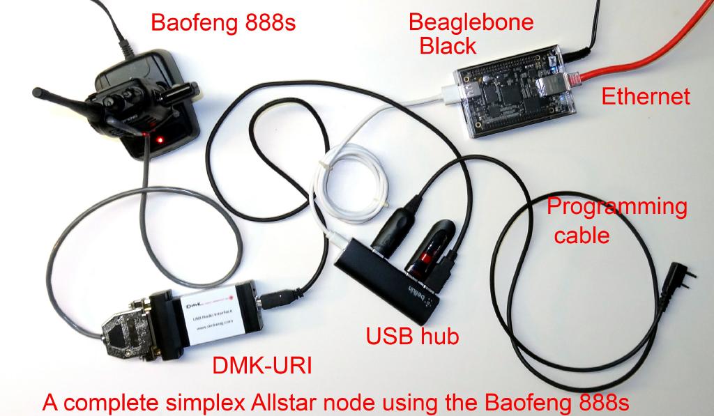
The Baofeng 888 is probably one of the best for the price transceivers to use as an Allstar node radio. Prices in quantities have gone as low as $8 in early 2017. Keep in mind this transceiver would generally only be used for a local node within your neighborhood or within a mile or so of where it is located. The 888 is also the ideal choice for a portable node and it makes a great second local node to augment a primary wider area simplex or repeater node.
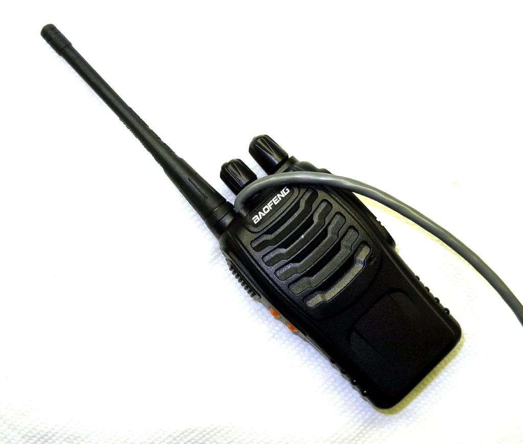
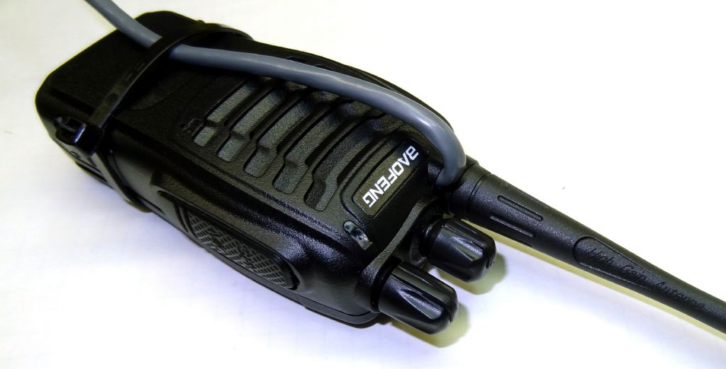
The Baofeng 888s is a UHF 16 channel basic transceiver. It has no display and requires programming via a serial or USB to serial cable. The cable is compatible with a Kenwood programming cable such as one used on a THF6. Chirp works fine to program the 888. The transceiver is available for about $17 on Ebay and delivery is fast.
Disassembly
See the update below before you disassemble!
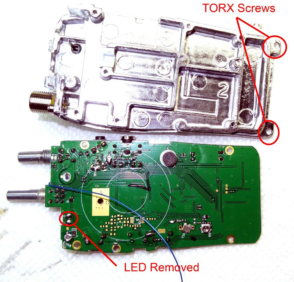
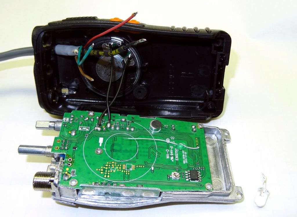
The transceiver is easy to disassemble. After removing the battery Two TORX screws at the bottom hold the chassis at the bottom so you will need a TORX driver set. You can get these at Home Depot or Lowes if you don't have one. First remove the antenna, and two knobs, and then remove the rings screwed onto the three shafts. I found them to be loose and a small screwdriver could be used to turn them off. You could also use a pair of needle nose pliers. Then remove the TORX screws at the bottom and pry up the metal frame from the case at the bottom. The whole thing should pull up and slide out but be careful as the speaker wires are connected. Unsolder the speaker wires and you should have the frame and board in your hand.
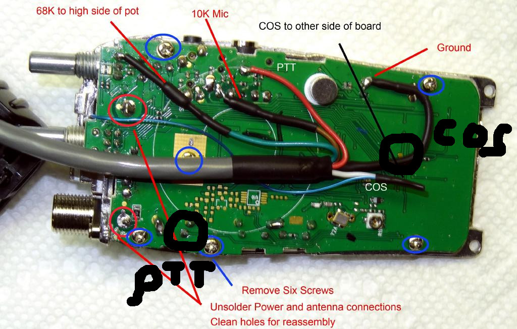
Now you need to remove the board from the frame. This requires the removal of 6 screws and unsoldering the power and antenna connections. See the photo for locations.

Making Connections
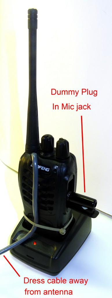
The only difference between this modification and others I have seen is that I do not remove anything from the transceiver except the LED. The LED is removed to facilitate the use of its opening in the case for the wire to the URI. In addition the RX audio wire is connected to the hight side of the pot. The side closest to the board edge. It is a much better idea to not connect at the speaker where more distortion and also level changes by the volume pot could take place. The value of the resistor is changed to 68K from the high side of the pot to the URI. The speaker works normally with the volume control and you can monitor incoming traffic on the node. The mic is muted by inserting an unconnected miniature (stereo, 3 conductor NOT 2 conductor) phone plug (larger plug) into the side of the radio. The rest of the photos should be self explanatory.
UPDATE!
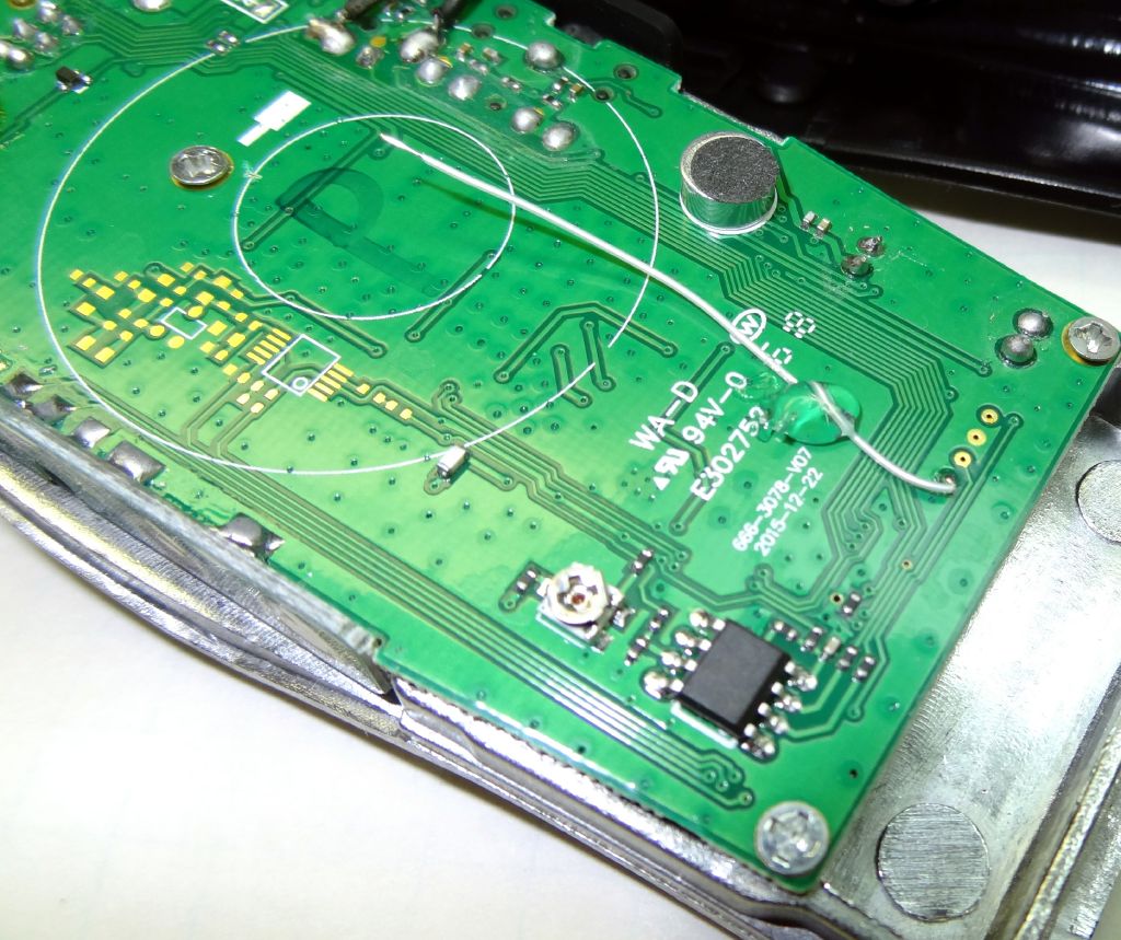
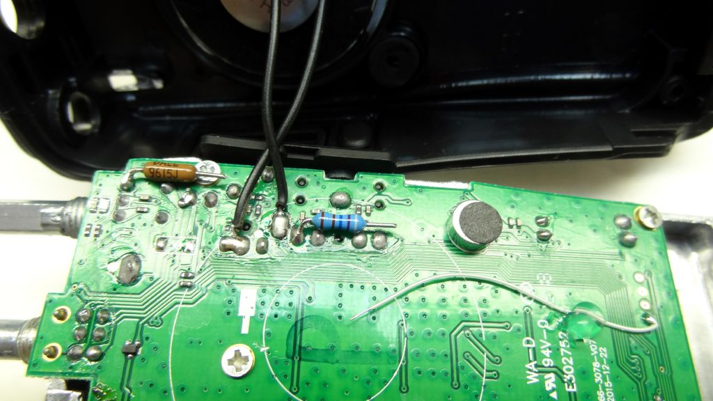
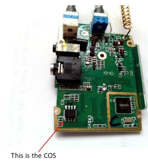
Frits, W1FVB forwarded to me this photo showing an easier way to pickup the COS line. NO disassembly of the circuit board is needed! No screw removal or unsoldering! Disregard those instructions and make all the connections on the solder side of the board. See the photo below for the connection point. The white wire shown connected to the smaller blue wire to the other side of the board instead simply connects to the point shown in the circle labelled COS.
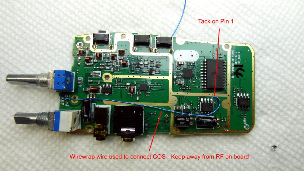
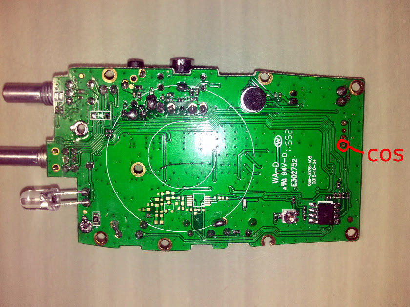
The 888 seems to have gone through several board revisions. Here is another photo that Frits sent showing an alternate place to pick up COS. If you board looks like this give it a try. You should use small (wire wrap type) wire and just tack it on these small pads. Don't apply too much heat. Once soldered put a dab of silicone on it to give it extra support.
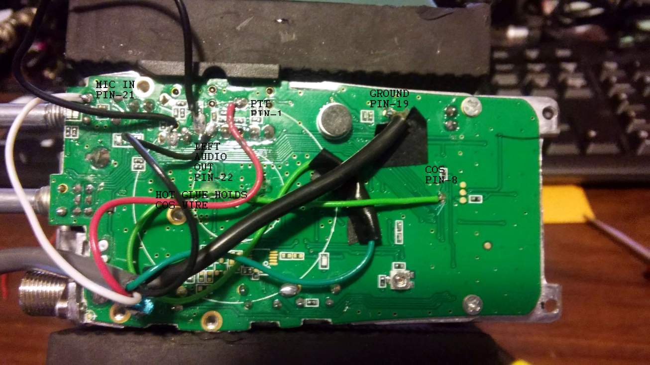
Here is a photo from KB2AYS on his mod using the simpler approach. Note he has labled the connections referencing the FOB end. The lead labeled "mic in" goes to the mic in on the FOB and is the RX audio FROM the 888 high side of the volume pot. The lead labeled 'Left audio out' is audio out FROM the FOB to this solder land which is the mic input of the 888. Pin numbers refer to the DMK-URI. If using a cheap sound FOB just use the audio (RED) mic in and (GREEN) audio out on the FOB.
K9CWM investigated a recent (June 2016) 888 design and provided this photo and notes on the connection locations and voltage levels.
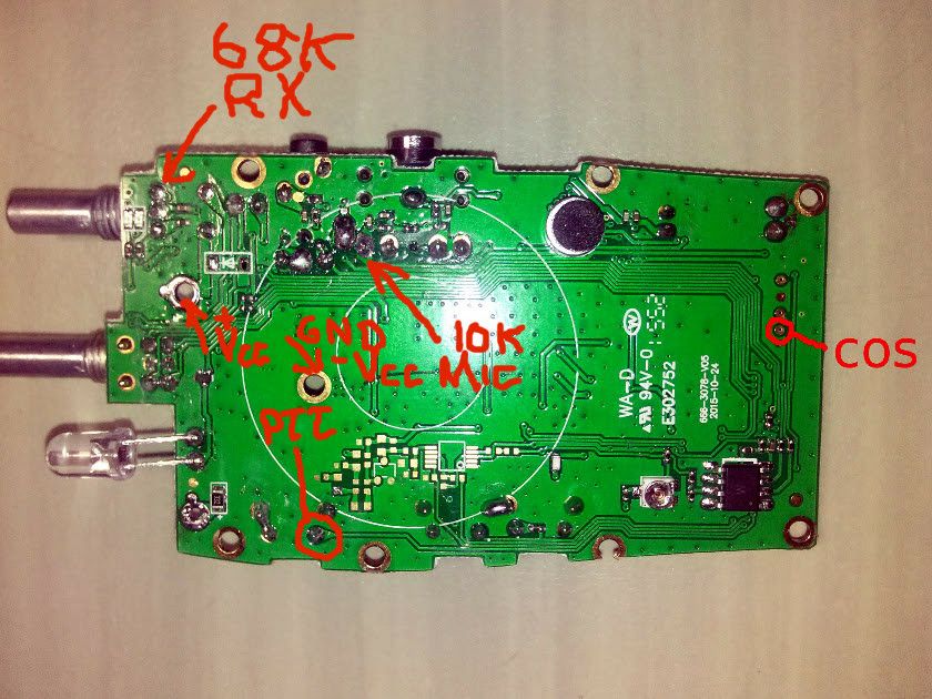
- The +Vcc point (~+4.1 VDC) on the radio is hot all the time battery is attached.
- The Mic audio is active all the time and is independent of PTT/COS high or low.
- COS goes high (~+3.5 VDC) when PL is detected.
- -Vcc pad area can be scraped off to solder to Gnd.
- Rx audio active when received audio active otherwise ~0 VDC.
Another Modification by WA3DSP
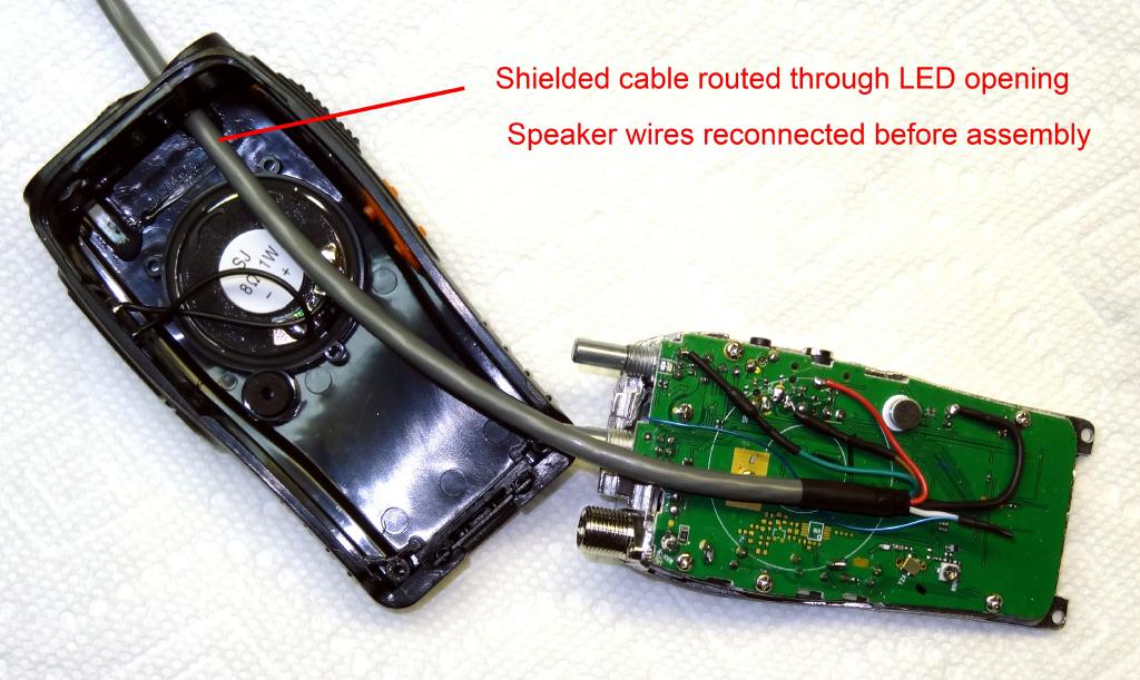
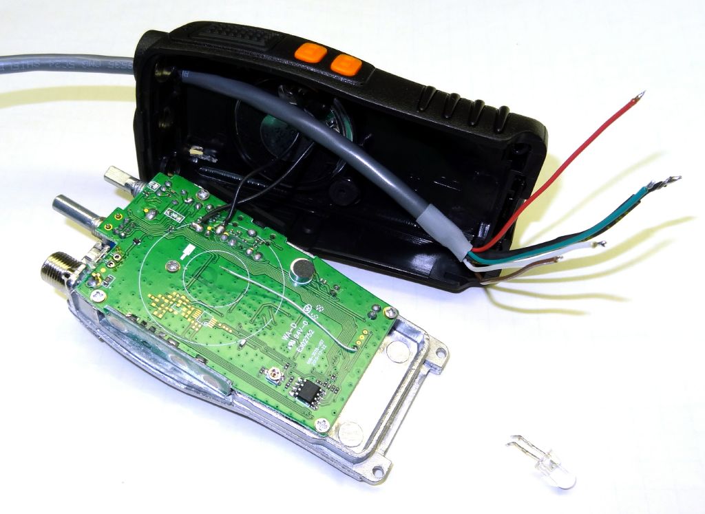
I ordered two more 888's and since it has been awhile since I mod'ed my first one I re-documented it again this time August 14, 2016. The radios I received followed several of the above photos so refer to them for reference. Here is what I did. First disassemble the radio as above and remove the LED. I used solder wick and it came right out. If you should ever desire to reinstall it save the LED in a safe place otherwise throw it in the junk box. There is no need to disconnect the speaker in fact it is desireable not to. If you don't jerk things around during this process the speaker leads will not pull off.
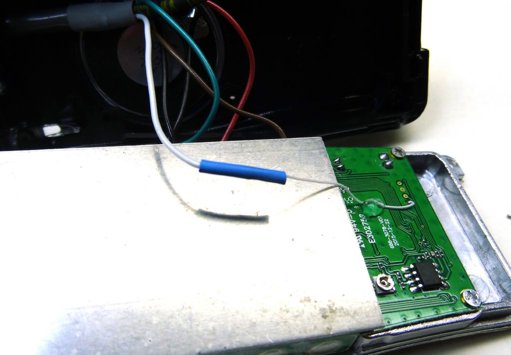
For the COS connection I used #30 wire-wrap wire and a blob of hot glue to secure it. Then Prepare a cable. I used some 5 conductor shielded cable I had laying around but an old USB cable would work. You need 4 conductors and a shield minimum. As you can see in the photo I slid some heat-shrink over the end of the cable after sliding it into the hole where the LED came through.
Resistors added and waiting for connections.
68K to audio pot (left) and 10K to mic (right)
Do NOT use a heatgun on shrink tube without a shield.
Temperatures can get quite high and knock surface mount parts off the board!
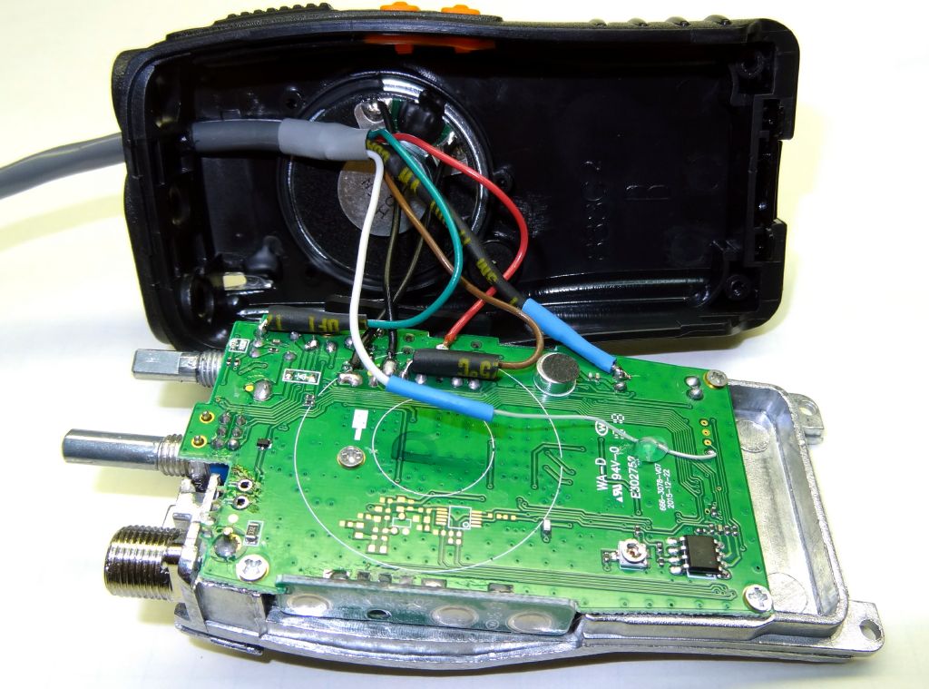
Everything wired and ready to close up. Colors I use are COS (white), PTT (red),
RX audio out (green), TX audio in (brown), shield and black connected (ground)
Completed modification. Note the wire is dressed down the radio and wire tied AWAY from the antenna. Prior to doing that motor-boating appeared on TX. Routing the leads properly should eliminate any need for bypassing. Also in a portable node it might be best to remote the antenna away from the other electronics.
Late 2016 BF888 version
In late 2016 yet another BF888 board design is being used. It is much smaller and the transceiver themselves are getting even less expensive. Here is a link to a PDF of the new design modified by WB3DZZ.
Final notes
The resistor values selected get the RX and TX audio level values very close to the 500 mid range default setting in simpleusb-tune-menu. Some tweaking may be necessary. In simpleusb.conf set rxboost=1 and carrierfrom=usb
I would recommend using the low power setting especially on a busy channel. UPDATE - the 888 has no high/low power even though the programming shows it. The output is about 1W in high or low mode.
CAUTION - this radio uses carrierfrom=usb which means that the COS line goes high with signal. If you disconnect (or maybe even turn off) the 888 transceiver from the USB FOB there is a good chance the COS line will float to a high value and trigger valid COS and hang up a channel if you are in a connected state. Never disconnect or turn off the transceiver when you are connected to other nodes. In addition if the 888 is running from the battery inserted in its charger the battery will eventually fail on a busy channel. The charger puts out less then the TX load. When this happens the COS will go high and hang a channel if connected. It is NOT a good idea to run the 888 from a stock battery and charger as a node radio.
I had a problem with motor boating in the Baofeng speaker on TX that seemed to be associated with RF feedback. I thought that bypassing one or both audio lines would fix it but it had no effect. It turned out the PTT line when bypassed with a .01uf cap eliminated all problems. Ideally this cap should go on the board but it also seemed to work fine at the DB25 end.
It turns out that even on low power and in the charger on a busy channel (we have some people that go for hours non-stop) the battery eventually wears down. If you have the voice prompts turned on the voice you hear in the speaker like "replace battery" will also go out over the nodes you are connected to. This is because the COS signal is asserted when the voice prompts are sent. You can turn the prompts off in the setup settings in Chirp. Ideally you should run the transceiver from an external supply - 3.7 volts - using a regulator from a 12V or 5V source.
Some additional suggestions - A 5V 2A wall wart with 2 diodes in series on the + lead works well as a power supply. This gives you a voltage close to the 3.7 volt battery. Also many of you probably have several old USB cables laying around. They make good connection cables for the audio, PTT, and COS lines from the radio to the FOB. They are well shielded. Cut off the ends and you have the required 4 wires and a shield. Also a user has installed the resistors at the connector end of the cable rather than inside the radio with success so this is also an option.
In my testing of the SA818 modules and the Baofeng 888 as node radios my preference is the Baofeng 888. It works well and has good audio. The SA818's have some annoying issues that aren't severe enough to not use them but overall in this price range I believe the Baofeng 888 makes a superior node transceiver.
Another version BF888 showing COS location
Here is another version that VK3JD came across in Australia in 2020. This shows the connection point for COS.
Power Supply Update
UPDATE 7/2018 - there is now an encapsulated 12V to 3.7 volt 3A car module available. This would make the power supply mod much easier. Here is the link -
A quick update on the power supply for the Baofeng 888. The battery in charger method works but it is not a good long term solution. Even on low power the battery runs down fairly quickly and although the transceiver keeps running it would be hard on the battery which would eventually fail. So I ordered a 12 volt car adapter for it from Amazon - $8.99 and free shipping.
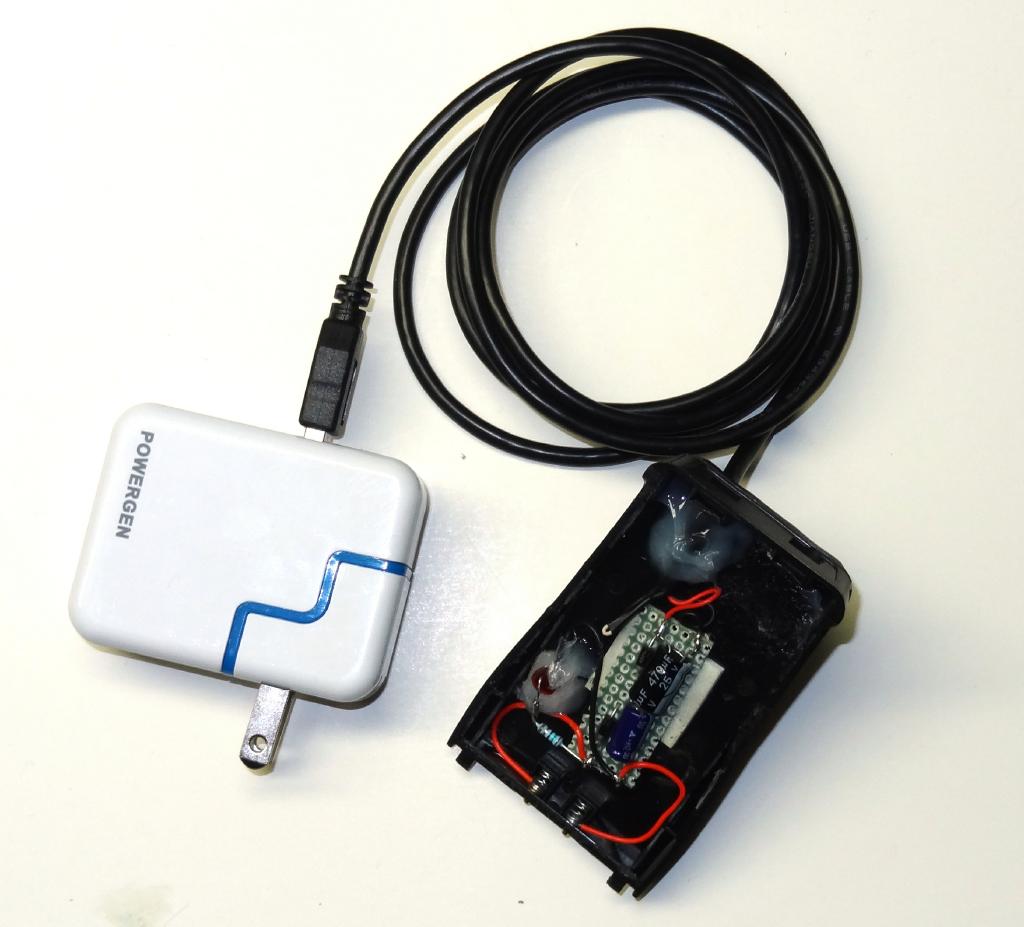
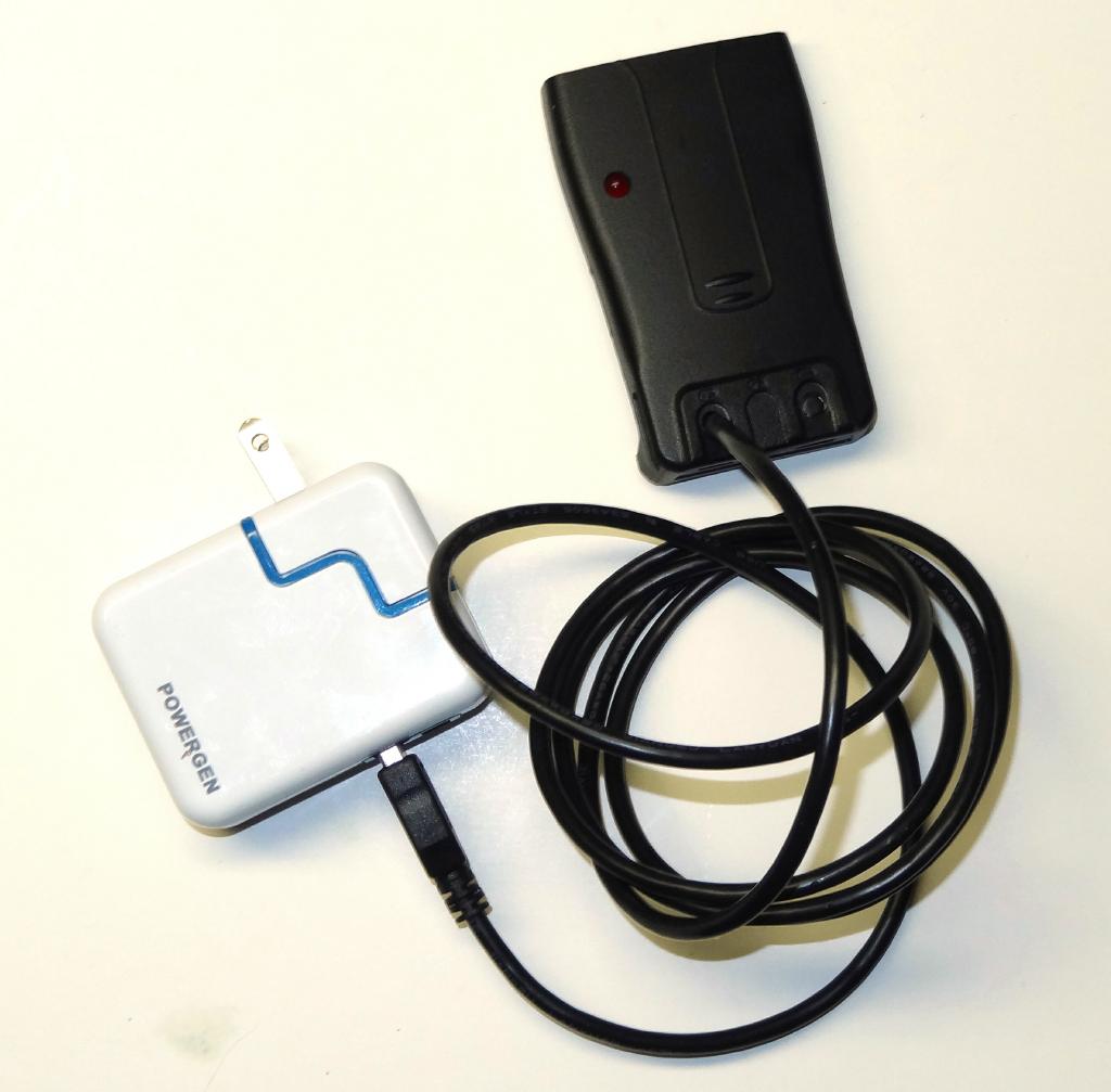
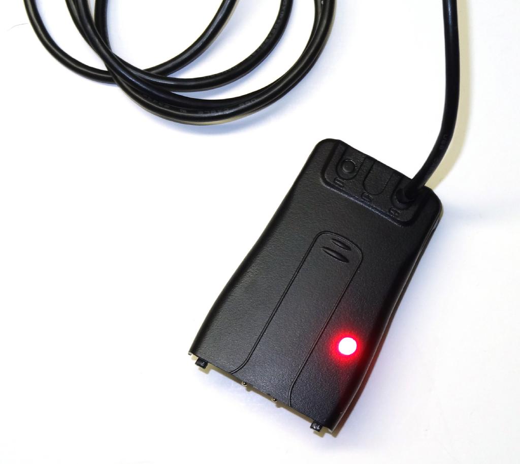
I really just bought it for the case as it connects like a battery to the 888. Internally the stock unit has a 7805 5 volt regulator with a diode reducing the output voltage to about 4.2 volts. The problem is when you run it on 12 volts there is a great deal of dissipation in the 7805 and even though it has a small heatsink it gets very hot. So I ripped everything out of it including the coil cord. To open the case take a small screwdriver and pry the cover off. I then used one of the USB to microUSB cables that comes with every BBB. I cut off the microUSB end. You will find four wires in the shielded cable. The white and green are data and are not used. They should be tied off and insulated. The remaining black and red wires are the 5V power. I made up a new circuit on a small perf board. It has two diodes in series with the positive lead and two capacitors, a 470uf on the 5V side and a 47uf on the 3.7V side. The actual voltage is dependent on the the diodes you are using, typically .7 volts drop per diode. I also added a red LED power indicator on the 3.7V side. I brought the new cable in from a hole drilled in the back of the case rather than the bottom where the original cable came in. This will allow you to set the transceiver upright if desired. The USB cable is plugged into a 1A or greater 5V wall wart. In the photos I am using a Powergen 2A unit. LATE UPDATE - I ended up removing (shorting) one diode. Two reduced the voltage to below 3.7 volts and the transmitter was working intermittently. Here is a schematic of the modified adapter -
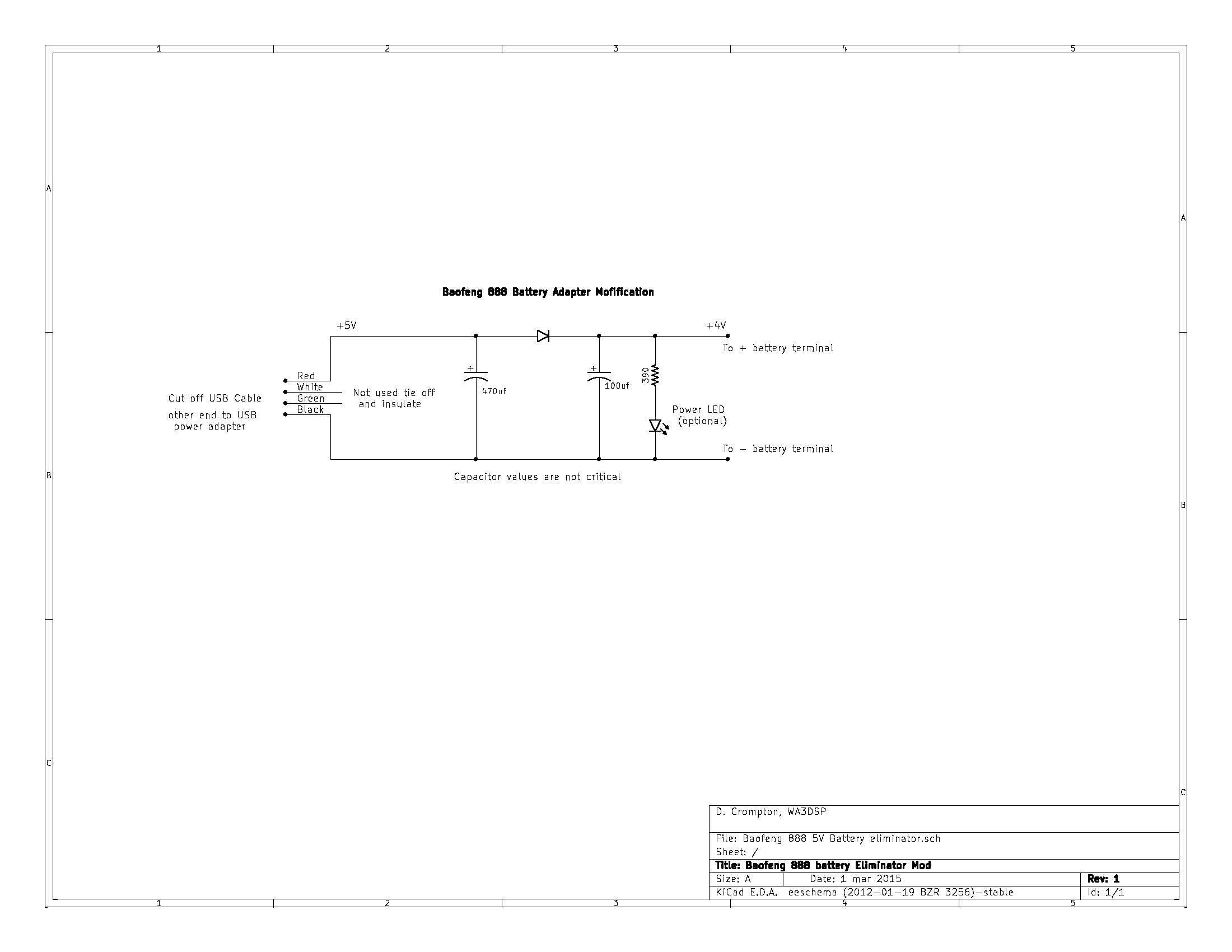
Click image for PDF schematic
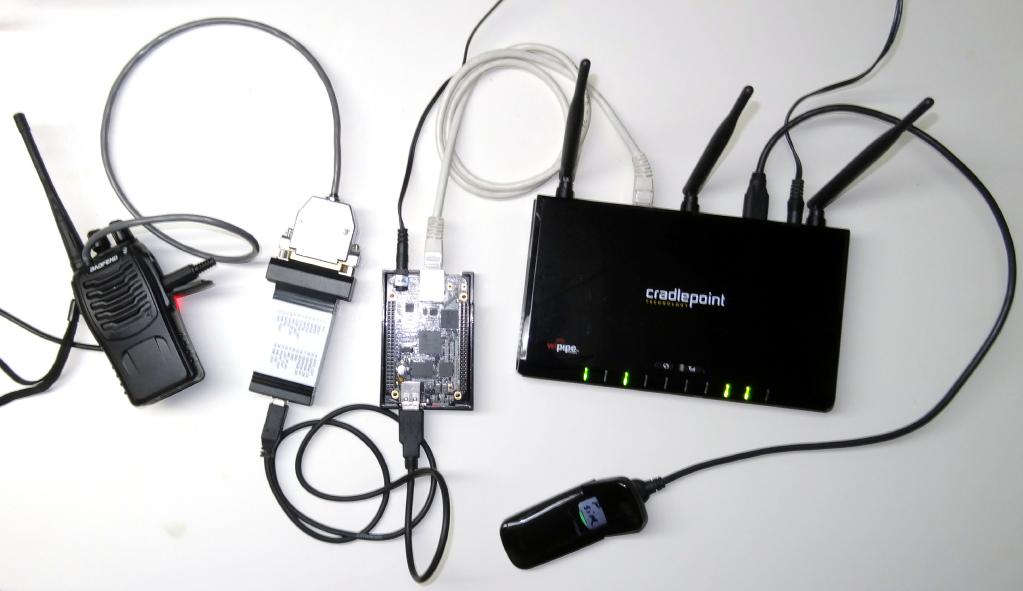
Using it mobile with a Cradlepoint Router and Verizon Aircard
I borrowed a Cradlepoint router with a Verizon aircard to do a demo and I decided to go on the road with it and see how it worked. I drove around the northern suburbs of Philadelphia through many cells and I was quite pleased with the results. Virtually no drop outs except very briefly at cell transitions. At no time were the transmissions lost. This would be a good way for on road travellers to get access to Allstar. I only did outbound connects as there was no port forwarding setup in the router. I was using 3g and I believe port forwarding would work if setup. The Cradlepoint router was model MBR1000. Keep in mind that in most cases this is a more expensive investment both in hardware and airtime compare to normal internet service but most of the US has 3g coverage but not always cable connectability. The Cradlepoint router has four Ethernet ports and also supplies wireless coverage. I know this has been done before but I wanted to check it out myself.
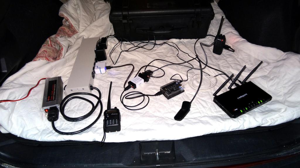
The next two photos show the installation in the back of my Subaru Outback. Power came from an inverter and outlet strip with two 5V wall warts for the radio and BBB and a 12V wall wart for the Cradlepoint. There is very minimal current draw from the battery. If one were to install this in a car or truck you would probably want to run it from a small battery that in turn was charged from the car. That way there would be no interruptions when the car was switched off and it would be well isolated from the cars power. A 12 Volt gel cell could probably run it all day. You could drive to work and have a node running outside in your car!
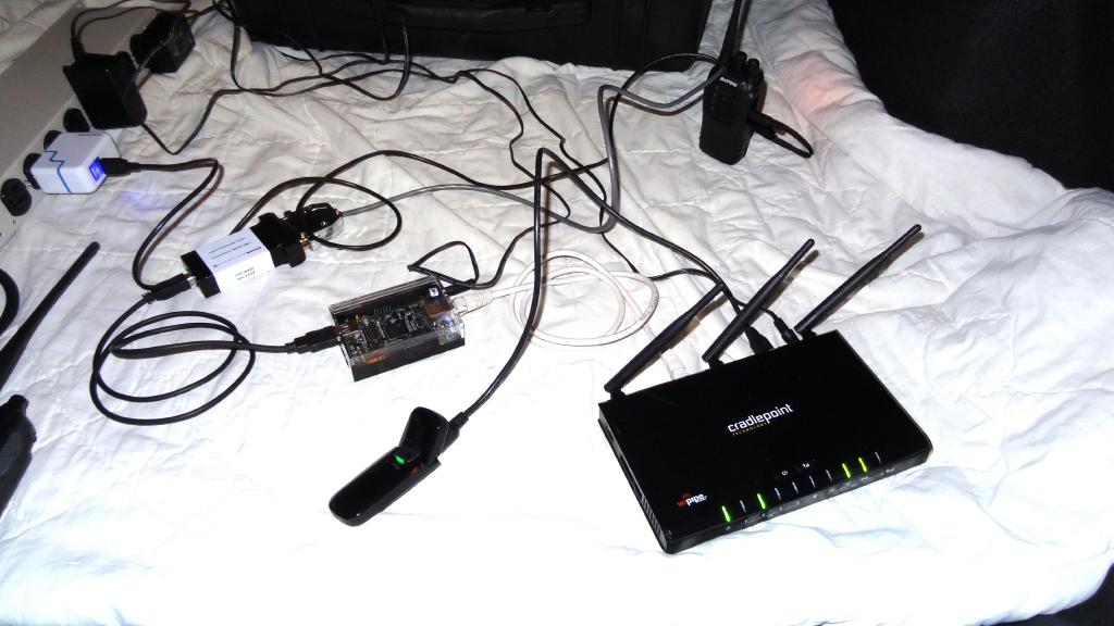
This is the same setup at my home to show a better view.
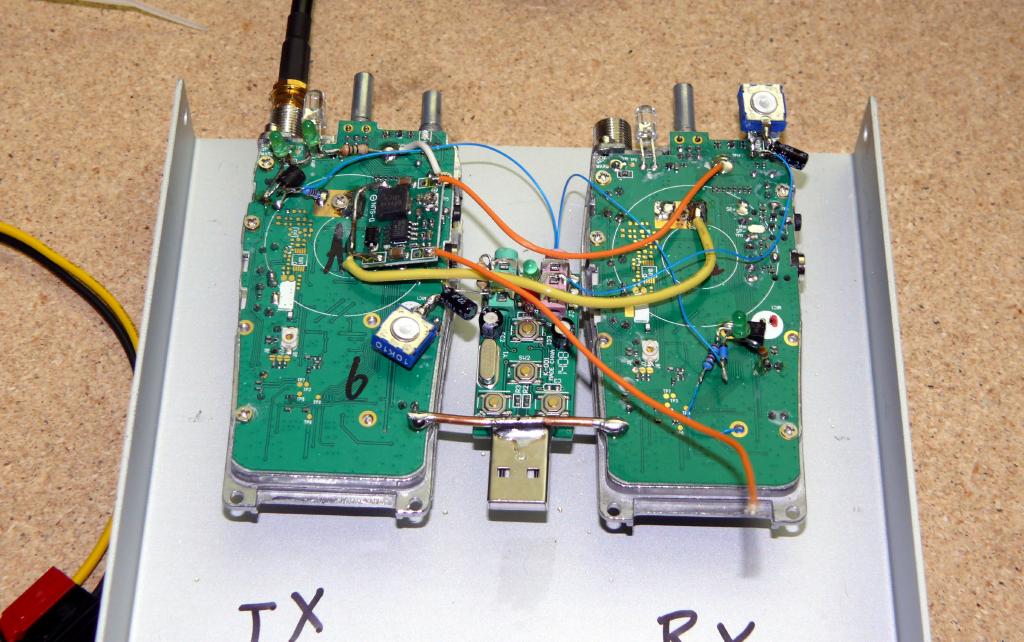
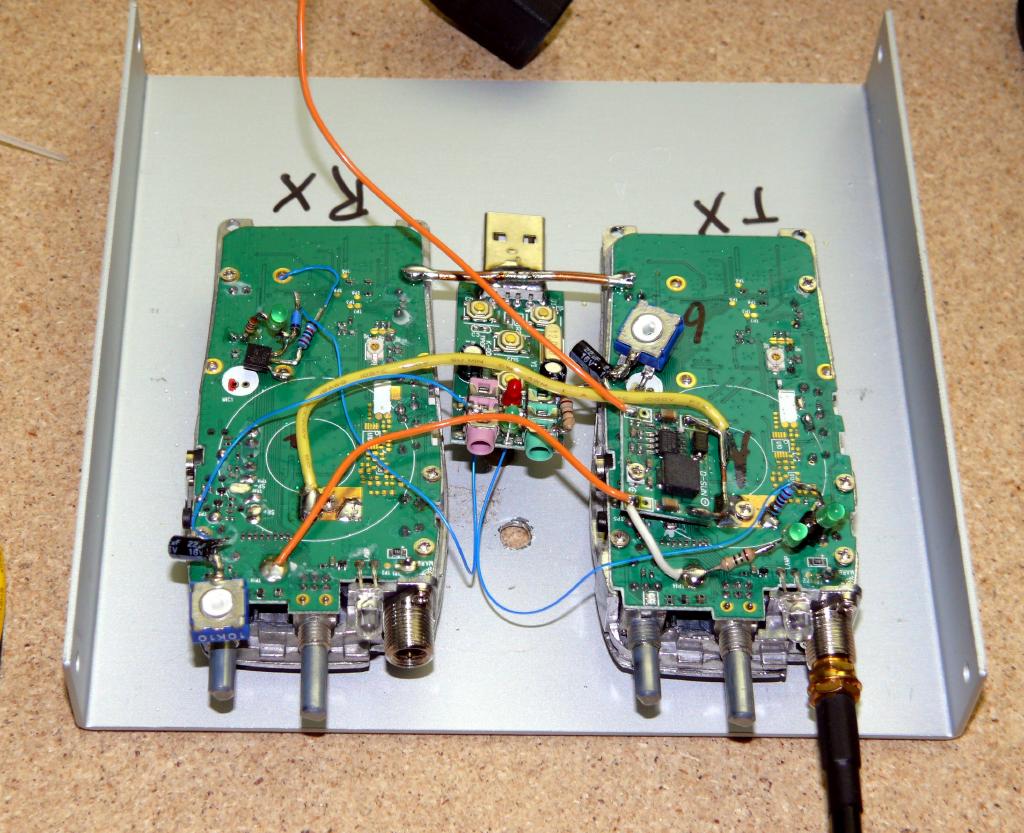
Building a Repeater with two BF888's
Here are two photos showing how Dave, KB4FXC built a $30 repeater using two BF888's.
Dave's comments -
Here are photos of my prototype BF-888 repeater that I finally got mounted
on a piece of scrap aluminum. It works well, with very good audio. My
next version will replace the volume pots with fixed resistors. Note that
I carefully kept the impedance low in the audio chain to reduce noise. The
headphone jack is terminated into 180ohms, the mic terminated into about
4K ohms.
Links
© 2016 - WA3DSP