Using the SA818 Module
as an Allstar Node Transceiver
Introduction and Purchasing
The SA818V, SA818U made by NiceRF and the DRA818V and DRA818U made by Dorji are VHF/UHF transceiver modules capable of wide frequency ranges and 1 watt of RD output. Thesae modules are made in China and are very inexpensive. Along with that goes some cautions about their use as stand alone they do no meet FCC requirements for an amateur transmitter. I will highlight some of the pluses and minuses of using these modules but the bottom line is that they provide a very inexpensive avenue towards getting an Allstar RF node on the air especially for local node use.
I choose the NiceRF module as the spec allows 5V operation. The Dorji spec show a lower maximum voltage which would require a reduction in a 5V supply. This could be supplied with a diode or two in series with the module power lead. It is also not clear if there really is any difference in the NiceRF and Dorji units as they have the same part number but apparently different manufacturers. There are a number of sources for the modules but all are from China and take several weeks or more for delivery. Prices range from $10 to $20 each depending on the quantity ordered and the source. It takes a little searching to find the best deal. These sites and deals are constantly changing. Here are a few examples of sites you can order from:
Things to consider
These are cheap Chinese made modules and there are some things to consider in using them. They should NOT be connected to an antenna without some form of filtering. The specification for transmitters in this power range is a minimum of 40db down relative to the carrier for any harmonic or spurious emission. Measured second harmonic content was anywhere from -22db to about -30db depending on the use of high or low power. The worse case being low power. I will show low pass filters that correct the problem nicely but also require some additional construction. Using the modules on a dummy load without a filter should be OK and would allow use in and around your home or wherever you want to operate however be aware of potential interference problems that could exist without using a filter. I would NOT run these modules in the high power mode for extended periods without some additional heat sinking and air cooling. The square pad on the SA818 near the antenna out end of the module is a place to apply a heat sink and is at ground potential.
The modules are very flexible allowing separate transmit and receive frequencies and tone codes, high/low power setting, RX output level, Pre/De-emphasis setting, high and low pass filters, and wide/narrow FM. That being said I have found a few annoying problems. The transmit signal to noise ratio is not very good. It is acceptable but not up to the standards we are use to with commercial and amateur equipment. There is noise on the transmit audio (what you hear listening to your node) that is worse on high power indicating some kind of internal chip interference or possible phase noise. This could be discounted for a local use node but I would not want to put this module on an amplifier and use it over a wide area. Another issue is the PL level. It seems high and is very noticeable on the transmit audio. There is no level adjustment. I tried the DCS (digital coded squelch) but the module DCS receiver response time seems slow. If you did not wait a few seconds before you talked it would cut off part of the audio. Most people would not wait and it would be annoying to the listener at the other end. Another annoying problem is that the first second or two of receive audio is distorted. It is like the RX does not recover properly after a transmission. I notice the overall audio quality to not be as good a other radios I have used. Your mileage may vary but these are all things to consider when deciding to use these modules.
Constructing a transceiver
The module needs some external components and a container to be functional. Since this is RF and should be shielded I choose a metal box. Adafruit has some nice tin boxes in the Altoid box style that work nicely. I especially like the fact that they can be directly soldered to allowing close ground connections and direct soldering of components to the chassis. They are available for $2.50 from Adafruit:
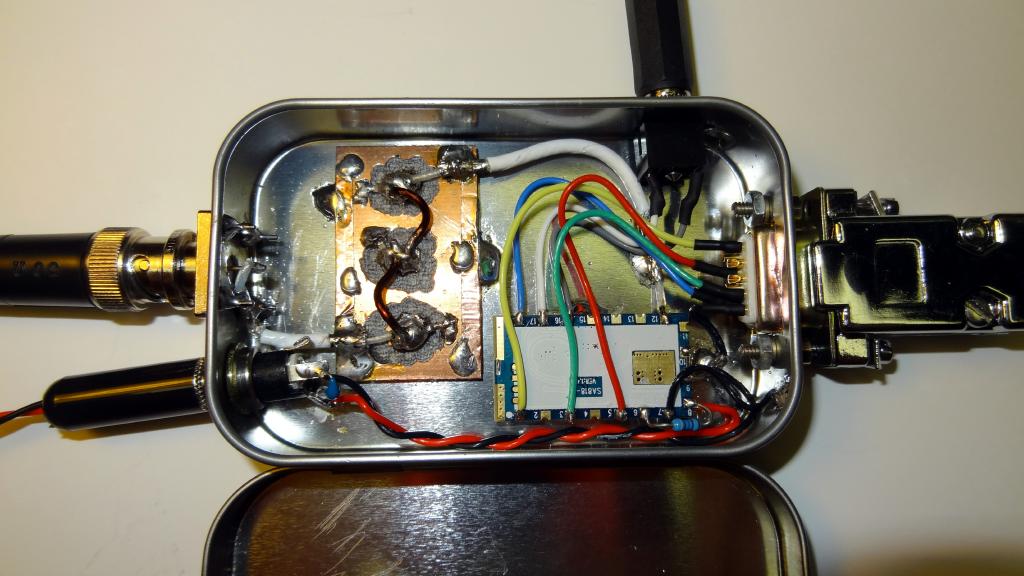
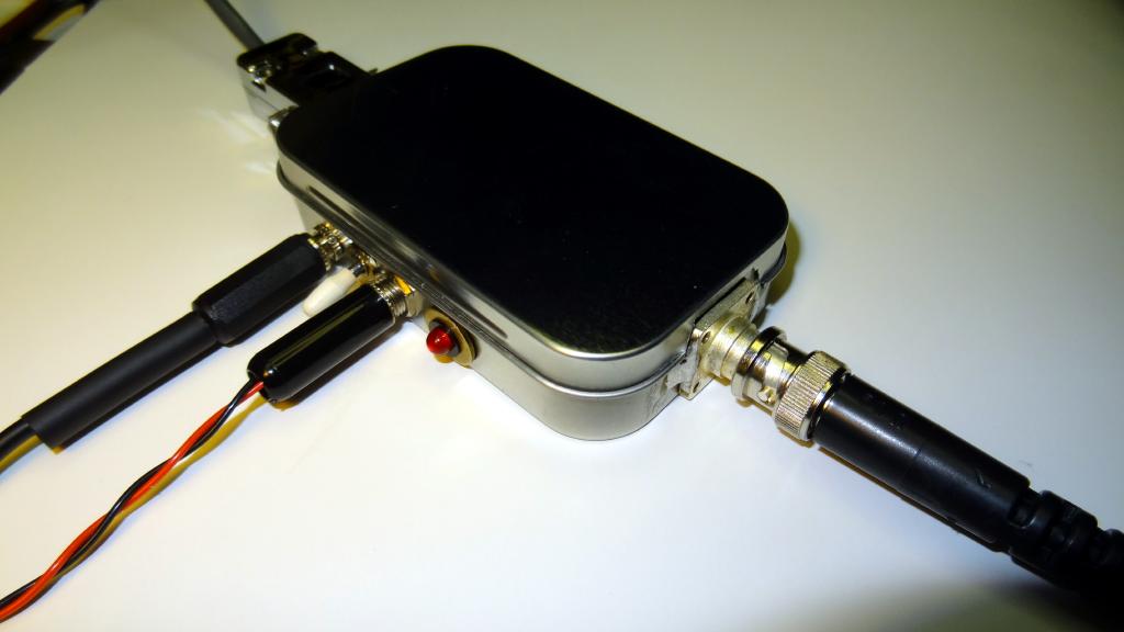
Here is what my first generation UHF box looked like.
The DB9 on the left is wired the same as the data jack on the Alinco DRx35 transceivers and the levels and signal polarities are the same allowing easy swapping with my Alinco transceivers. On the bottom left is a 1/8" mini stereo phone plug which brings in the serial RXD/TXD signals for programming. The connection is only needed for programming and can be disconnected during use. To its right is a power LED. The +5 power input is a coaxial plug on the upper right and the antenna connector is a BNC on the right.
Inside the SA818 module is mounted at the upper left. The shield of the module is tack soldered to the tin enclosure. A low pass filter was constructed on double sided copper board and is soldered to the tin on the right. Various low pass filter designs will be discussed below. The only discrete components are a 10K from +5 to pin 6 and a 10K from pin 18 to ground with a 47K and 10uf in series from pin 18 to the DB9. This sets the TX (mic in) level to equal those of the Alinco.
Second generation UHF transceiver construction
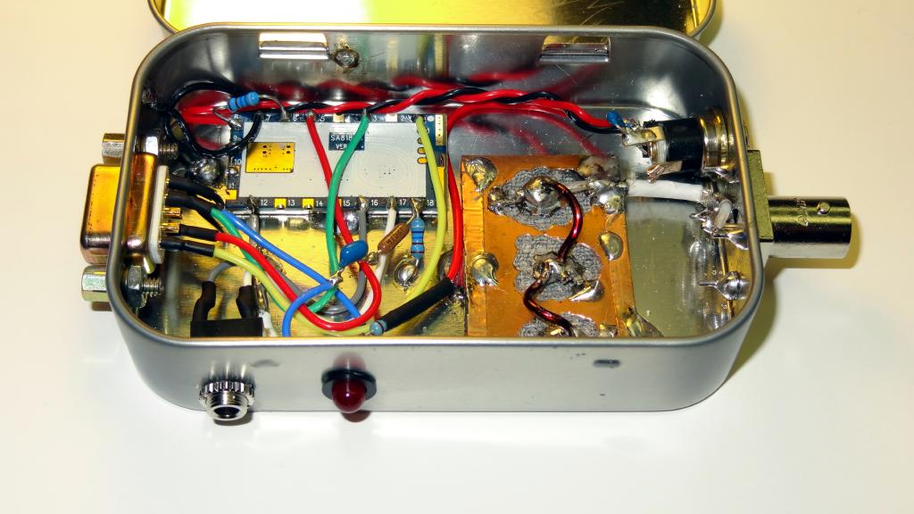
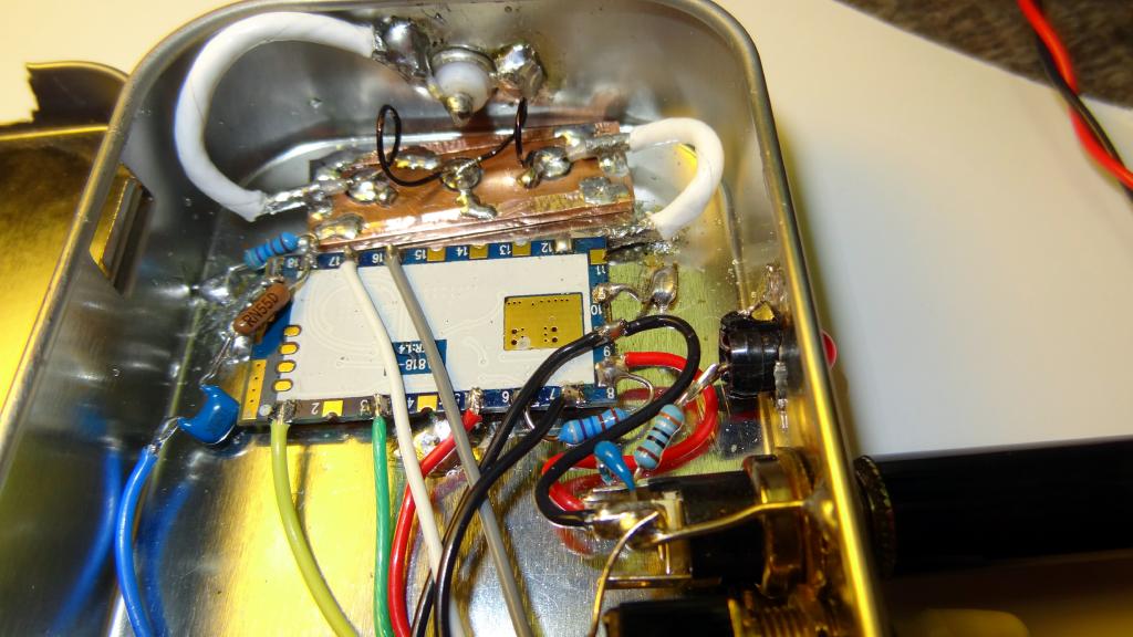
Here are some views of a second generation build of the transceiver. Slight modifications were made including a power level switch and a smaller low pass filter design.
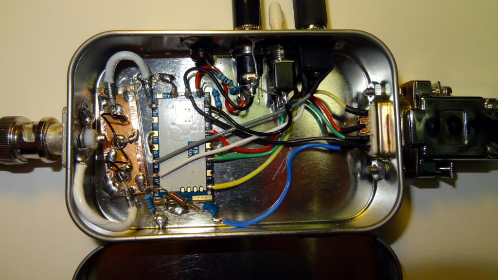
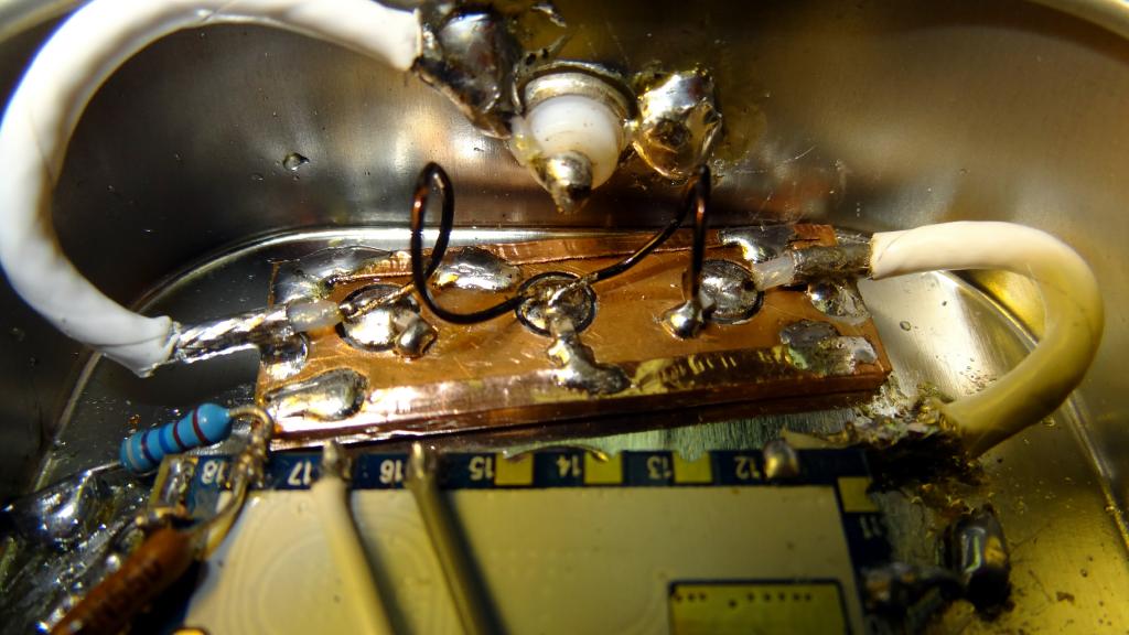
Closeup views of the low pass filter assembly. The filter consists of two inductors and three capacitors. The inductors are 1 turn of #22 wire about .2 inch in diameter. Theses are wired in series across three isolated pads on the copper board. The outer pads have a 10 pf chip capacitor to ground and the inner pad has a 15 pf to ground. Either end could be input or output. The first generation filter used #15 wire and a larger board with milled pads rather than pads cut in nice circles. Both filters worked equally well for the intended purpose with the larger #15 filter being slightly better in the stop band. Copper tape is wrapped around the double sided board and then soldered to the tin chassis.
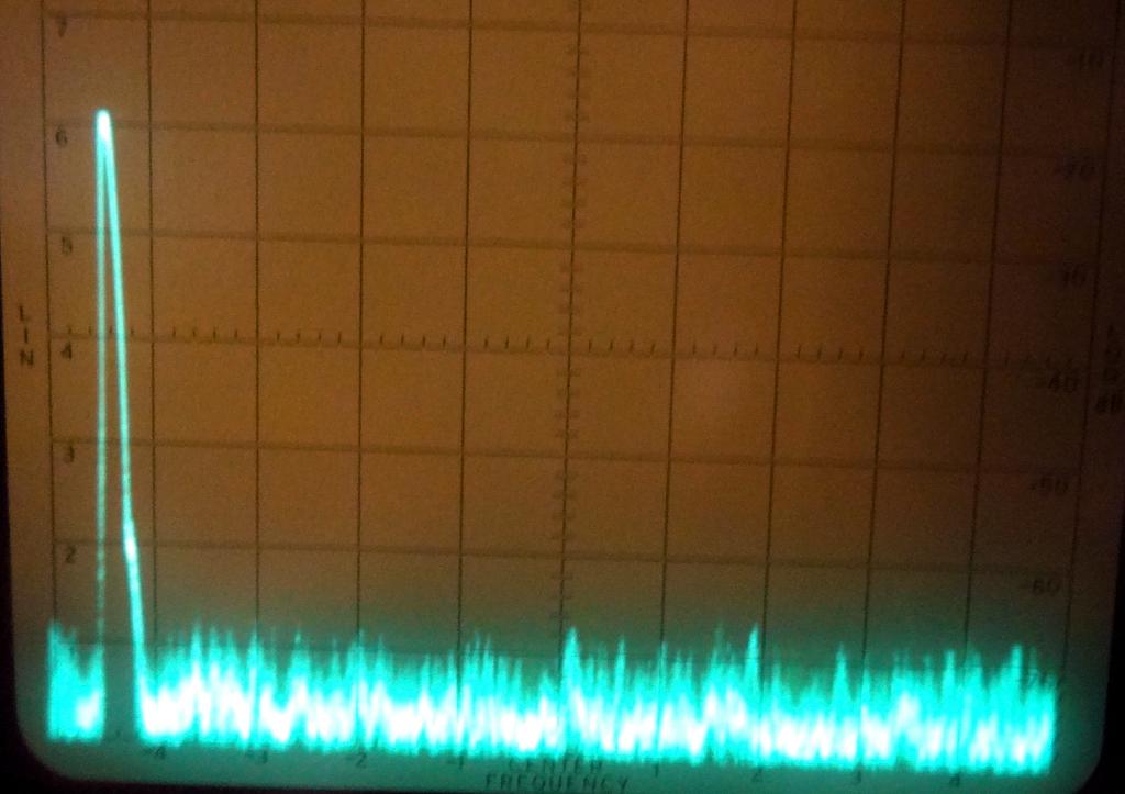
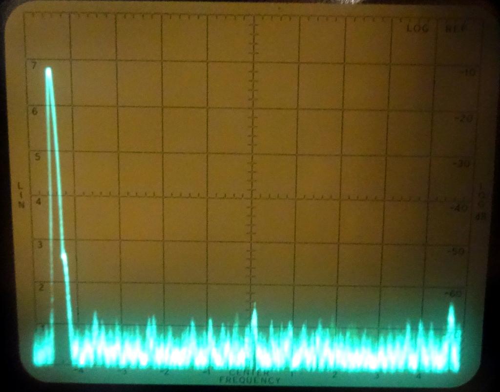
Before and after spectrum displays
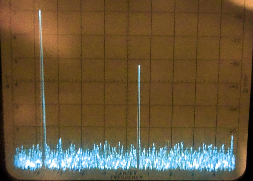
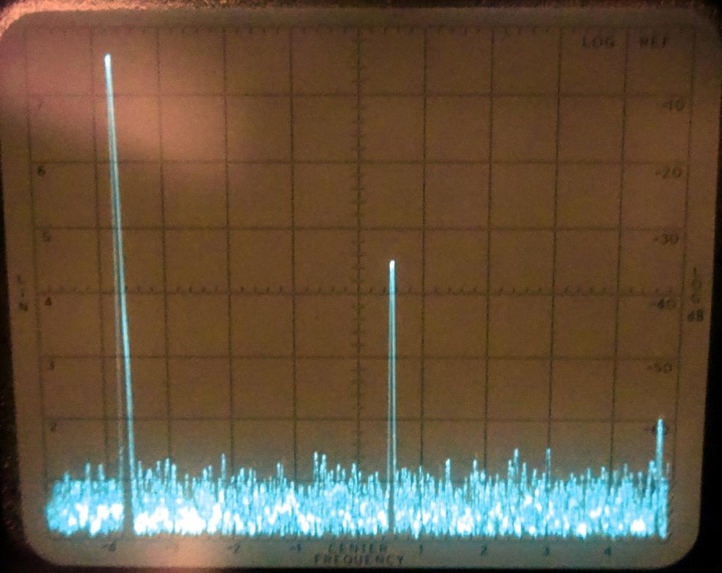
Here are some spectrum analyser displays of the UHF output before filtering. The frequency used in these displays is 431.1 Mhz. The analyser is 10db/div vertical and 100Mhz/div horizontal. The first display is low power and the second is high. On low power the 2nd harmonic is about 22db down and on high power about 30db down. In both cases the 3rd harmonic and any other spurious emissions are well below acceptable levels. The displays are not calibrated for absolute readings. Fundamental loss was less than a db and barely noticeable on a wattmeter.
And here are displays using the low pass filter. The first is low power showing the harmonics to be well below 45db down and the second display showing high power to be well below 50db down.
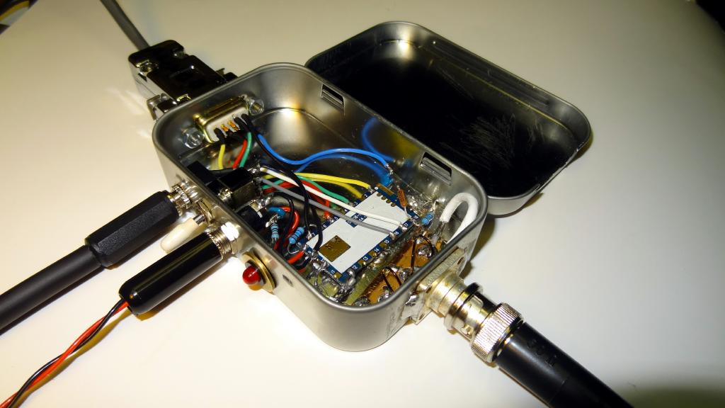
Closed view of the transceiver case
Programming
Programming the 818 modules requires a serial interface. Since the current version of BBB Allstar (1.2.1) does not support direct board I/O a USB to serial interface can be used. The Adafruit model works very well on the BBB. I use it with a USB hub and it can be installed just by plugging in as needed. The Adafruit unit has 4 wires. RXD, TXD, +5V and ground. I wired the RXD,TXD and ground to a mini stereo plug. The +5 is not used. The programming takes only a few minutes and is very simple thanks to a Python program written by Chris, W0ANM. The code is designed to install on the BBB and will be included in the next version of the BBB Allstar code. Once installed there are two Python programs 818-prog and 818cli-prog. Beginners should use the 818-prog version as it steps you through the settings. Just be sure to follow the format and it should program fine. The 818cli-prog is for command line entry of the entire programming string for use in scripts etc. Here is a link to the Adafruit interface and the W0AMN blog which has more information on the 818 and shows his method of packaging the module.
- Adafruit USB to Serial Adapter
- An Inexpensive (not fake) FTDI USB to Serial Adapter
- W0ANM blog - module programming information and code
Allstar Considerations
There are no special Allstar configuration options required for these modules other than the normal simpleusb.conf configuration and level settings using simpleusb-tune-menu. I wired the modules with a DB9 to match the Alinco data port configuration. With the resistor values and wiring shown above the level setting roughly matches that of the Alinco radios. This is with the simpleusb.conf settings of rxboost = 1, and carrierfrom = usbinvert. Also when programming the SA818 the RX level was set to 1. Using the DMK URI USB FOB Levels settings were - Menu item 2 - RX = 750 and item 3 - TXA = 700
Building a Repeater
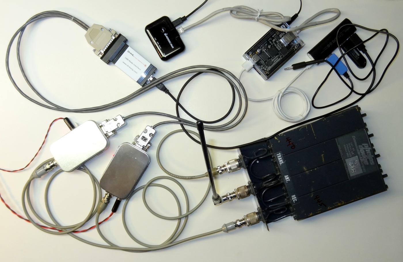
I have built a mini repeater using two of the SA818's, my first and second generation boxes shown above. It works quite well and overcomes the problem with receive audio distortion in the first few seconds when returning from transmit. When using the modules in a repeater one SA818 only receives and the other only transmits thus eliminating the TX to RX problem within the module. Here is a photo of the complete repeater.
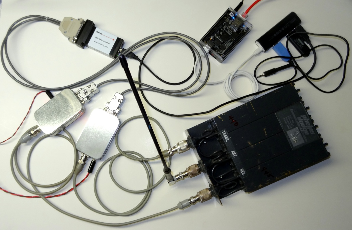
The photo shows the transceiver boxes to the left. Both are fed with 5V. Their antenna in/out goes to the Phelps Dodge duplexer and a whip antenna is connected to the center antenna terminal. The transceivers are connected to a DMK-URI USB interface to a USB HUB to the Beagle Bone Black. Also plugged into the hub is a 32GB Memory card, used for backups, and a USB to serial adapter, used to program the transceivers The next photo shows the same repeater only using the IOGEAR wireless Ethernet adapter. The entire repeater could be made portable with a battery and regulator supplying the 5 volts.
Conclusion
I hope you find this article helpful in your construction of a cheap but usable VHF/UHF transceiver for use with Allstar or general communications. I will be building a VHF version and I will add photos and details on that to this page in the near future.
© 2014 - WA3DSP